Press Brake Control Software: Optimizing 2D and 3D Bending

In the modern fabrication shop, the efficiency of a press brake is no longer determined solely by its hydraulic tonnage or frame rigidity. Instead, the bottleneck—or the competitive advantage—lies in the press brake control software. As sheet metal components become increasingly complex, with intricate flange geometries and tight tolerance requirements, the ability to program, simulate, and execute a bend sequence accurately has become paramount. This article explores the transition from traditional 2D graphical interfaces to advanced 3D simulation environments, examining how these digital tools minimize scrap, reduce setup times, and empower operators to achieve first-part-correct production.
Understanding the Basics of Press Brake Control Software
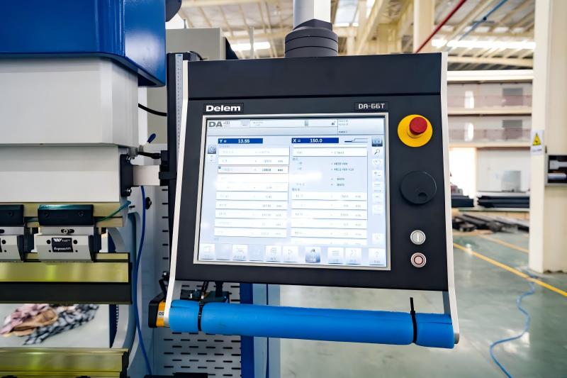
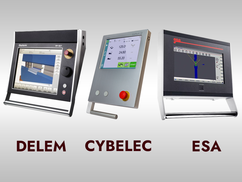
Press brake control software serves as the human-machine interface (HMI) that translates engineering intent into physical motion. Historically, press brakes were operated via manual backgauge settings or simple numerical controllers where operators input X and R axis coordinates. Today, modern CNC (Computer Numerical Control) systems, such as those from Delem, Cybelec, or ESA, provide a graphical environment that automates these calculations.
At its core, the press brake control software manages the synchronization of the Y1 and Y2 cylinders to ensure the ram remains parallel or tilted to a specific degree. It also controls the multi-axis backgauge system, which can range from a simple 2-axis (X, R) setup to a complex 6-axis (X1, X2, R1, R2, Z1, Z2) configuration. The software uses algorithms to calculate the necessary force, the depth of the punch into the die (to achieve a specific angle), and the optimal sequence of bends to avoid collisions with the machine frame or tooling.
The transition from manual calculation to real-time 3D simulation represents the single greatest leap in metal forming productivity over the last two decades, effectively decoupling part complexity from setup time.
Why Press Brake Control Software Matters in Sheet Metal Fabrication
The practical significance of advanced control software cannot be overstated. In high-mix, low-volume (HMLV) production environments, the time spent on ‘test bends’ and manual programming is a significant drain on profitability. Modern software addresses several critical pain points in the fabrication workflow.
- Scrap Reduction: By accurately calculating the bending allowance and simulating the process, the software ensures the flat pattern is correct before the first cut is made.
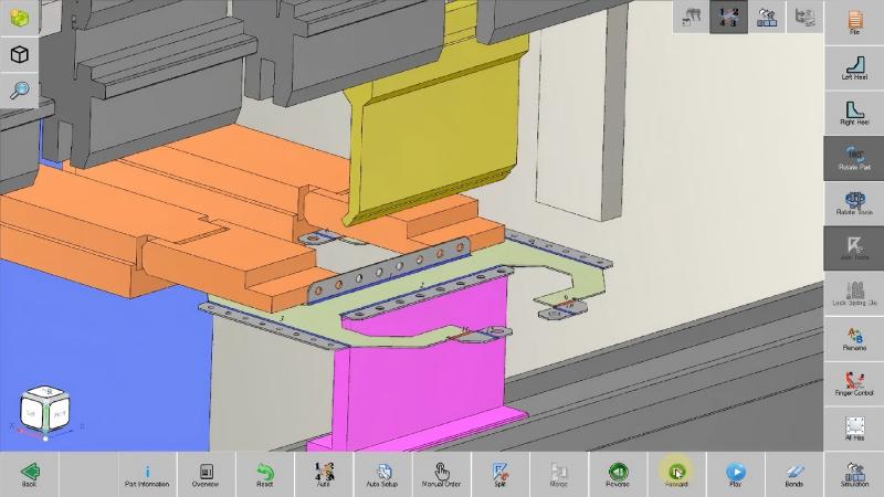
- Collision Prevention: 3D simulation identifies instances where the part might hit the ram, the tools, or the backgauge fingers, preventing costly damage to equipment and materials.
- Skill Gap Mitigation: Sophisticated software guides less experienced operators through the bending sequence with visual cues, reducing the reliance on highly specialized master fabricators for every job.
- Production Predictability: With offline programming (OLP), engineers can determine the feasibility of a part before it ever reaches the shop floor.
Key Factors to Consider in Press Brake Control Software
When evaluating a new press brake or upgrading an existing system, engineers and factory managers must look beyond the screen size. The following technical factors define the capability of the control system:
1. File Compatibility and Integration
The ability to import native 3D CAD files (STEP, IGES, SAT) is essential. The software should be able to automatically ‘unfold’ these 3D models into accurate flat patterns based on the specific tooling available in the shop.
2. Automatic Bend Sequencing
Advanced algorithms should suggest the most efficient sequence of bends. This includes calculating the minimum number of part flips and rotations, which directly impacts the cycle time and operator fatigue.
3. Tooling Library and Management
The software must maintain a comprehensive database of punch and die geometries, including their load limits, radii, and heights. This allows the system to calculate the ‘shut height’ and prevent over-tonnage situations.
4. Crowning and Springback Compensation
Modern controls integrate with mechanical or hydraulic crowning systems to compensate for bed deflection. Furthermore, software with integrated springback databases can adjust the punch depth dynamically based on material properties (e.g., Stainless Steel vs. Aluminum).
Technical Explanation: Calculations and Engineering Principles
The software operates on fundamental engineering principles of plastic deformation. One of the most critical calculations performed is the Bending Allowance (BA), which determines the developed length of the flat sheet. The software typically uses the following formula:
BA = pi * (R + (K * T)) * (A / 180)
Where:
R = Inside bend radius
K = K-Factor (ratio representing the location of the neutral axis)
T = Material thickness
A = Bend angle (in degrees)
Another vital calculation is the Tonnage Requirement (F). The software must ensure that the required force does not exceed the machine’s capacity or the tooling’s safety limit. The simplified formula used for V-bending is:
F = (1.42 * LTS * s^2) / w
Where:
LTS = Lower Tensile Strength of the material
s = Sheet thickness
w = Die opening width
Material Constant Table for Control Calibration
The following table illustrates how different materials and R/T ratios influence the K-factor utilized by the software for precision folding:
| R/T Ratio (Radius/Thickness) | K-Factor (Soft Materials) | K-Factor (Hard Materials) | Typical Application |
|---|---|---|---|
| Less than 1.0 | 0.33 | 0.29 | Tight radius air bending |
| 1.0 to 1.5 | 0.40 | 0.35 | Standard industrial bending |
| 1.5 to 3.0 | 0.45 | 0.40 | Large radius forming |
| Above 3.0 | 0.50 | 0.48 | Rolling or gentle curving |
Comparison: 2D Graphical vs. 3D Simulation Controls
Choosing between 2D and 3D control capabilities often depends on the complexity of the parts and the volume of production. While 2D controls are cost-effective, 3D systems provide a significantly higher level of process security.
| Feature | 2D Graphical Interface | 3D Simulation Environment |
|---|---|---|
| Visualization | Side-view cross-section only | Full isometric part and tool model |
| Collision Detection | Detects interference with tool profile | Detects interference with side frames, backgauges, and tools |
| File Import | DXF (2D lines) or manual entry | STEP, IGES, or direct CAD link |
| Programming Time | Moderate (requires manual logic) | Fast (automated bend sequencing) |
| Best For | Simple profiles, L-bends, U-channels | Complex boxes, multi-flange brackets, aerospace parts |
Step-by-Step Guide: The 3D Programming Workflow
To maximize the benefits of modern press brake control software, shops should adopt a structured programming workflow. This process is typically handled in an offline office environment (Offline Programming) to keep the machine running on other jobs.
- CAD Model Import: Import the 3D STEP file of the finished part. The software identifies the material type and thickness.
- Tooling Selection: The software analyzes the part and recommends the best punch and die combination based on the available inventory. It checks for ‘tooling clearance’ in deep boxes.
- Automated Unfolding: The software calculates the flat pattern using the shop-verified K-factors and bending deduction tables.
- Bend Sequence Optimization: The algorithm tests thousands of sequence combinations to find the one with the fewest collisions and part manipulations.
- 3D Simulation: The operator or programmer runs a virtual simulation. If the part turns red at any point, a collision is detected, and the sequence or tooling must be adjusted.
- Program Transfer: The finalized NC (Numerical Control) code is sent via the network to the press brake. The operator simply loads the tools as shown on the screen and begins production.
Common Mistakes to Avoid
Even with advanced software, engineering errors can occur if the following mistakes are not avoided:
- Ignoring Tooling Limits: Never assume the software will catch a tonnage overload if the tool data is entered incorrectly. Always verify the maximum Tons/Meter rating of your punches and dies.
- Using Default K-Factors: Default software values are averages. For precision work, conduct test bends for every material batch and update the software’s library with the actual results.
- Neglecting Backgauge Clearance: When bending small flanges, ensure the backgauge fingers have enough clearance to retract before the punch contacts the sheet.
- Skipping the Simulation: Operators sometimes bypass the 3D simulation to save seconds, only to find the part hits the machine frame on the fourth bend.
Industry Applications
The impact of 3D-enabled press brake control software is visible across various high-precision industries:
- Aerospace: Forming complex aluminum and titanium brackets where material costs are extremely high and scrap is unacceptable.
- Medical Equipment: Manufacturing stainless steel enclosures for diagnostic machines where aesthetic finish and dimensional accuracy are critical.
- Food Processing: Creating complex hopper designs with multiple non-90-degree angles that require precise bend sequencing to ensure weld fit-up.
- HVAC and Enclosures: Rapidly programming custom control cabinets and ductwork transitions where part variety is high.
In the era of Industry 4.0, the press brake is no longer an island of manual labor but a connected node in a digital manufacturing ecosystem.
Conclusion
Press brake control software has evolved from a simple coordinate entry system into a sophisticated engineering powerhouse. The transition from 2D graphics to 3D simulation has fundamentally changed the economics of sheet metal fabrication, making it possible to produce complex, high-precision parts with minimal setup and zero scrap. For manufacturers looking to remain competitive, investing in a robust control system—and the training to use it effectively—is just as important as the steel and hydraulics of the machine itself. By leveraging automated bend sequencing, 3D collision detection, and offline programming, shops can ensure that their bending operations are a source of profit rather than a production bottleneck.
FAQ
What is the difference between 2D and 3D press brake software?
2D software shows a profile view and is suitable for simple parts. 3D software provides a full volumetric model of the part, tools, and machine frame, allowing for comprehensive collision detection and automated bend sequencing for complex geometries.
Can I use 3D simulation software on an older press brake?
In many cases, yes. While the machine’s onboard controller might be limited, you can use Offline Programming (OLP) software on a PC to simulate the process and then transfer the simplified NC code to the older machine via RS232 or USB.
Why is a K-factor important in the software settings?
The K-factor determines where the neutral axis of the metal lies during a bend. If this is incorrect in the software, your flat pattern length will be wrong, leading to parts that are either too long or too short after bending.
Does the software automatically calculate springback?
Advanced software packages have springback databases or can be integrated with angle-measuring systems (like lasers) to compensate for material springback in real-time by over-bending the part to the precise required angle.
What file formats are best for 3D press brake programming?
STEP (.stp) and IGES (.igs) are the industry standards. STEP files are preferred because they contain more robust geometric data, making it easier for the software to identify bend lines and material thickness automatically.


