Press Brake Alignment Guide: Diagnosing Ram and Bed Parallelism Issues

Technical Overview of Press Brake Alignment
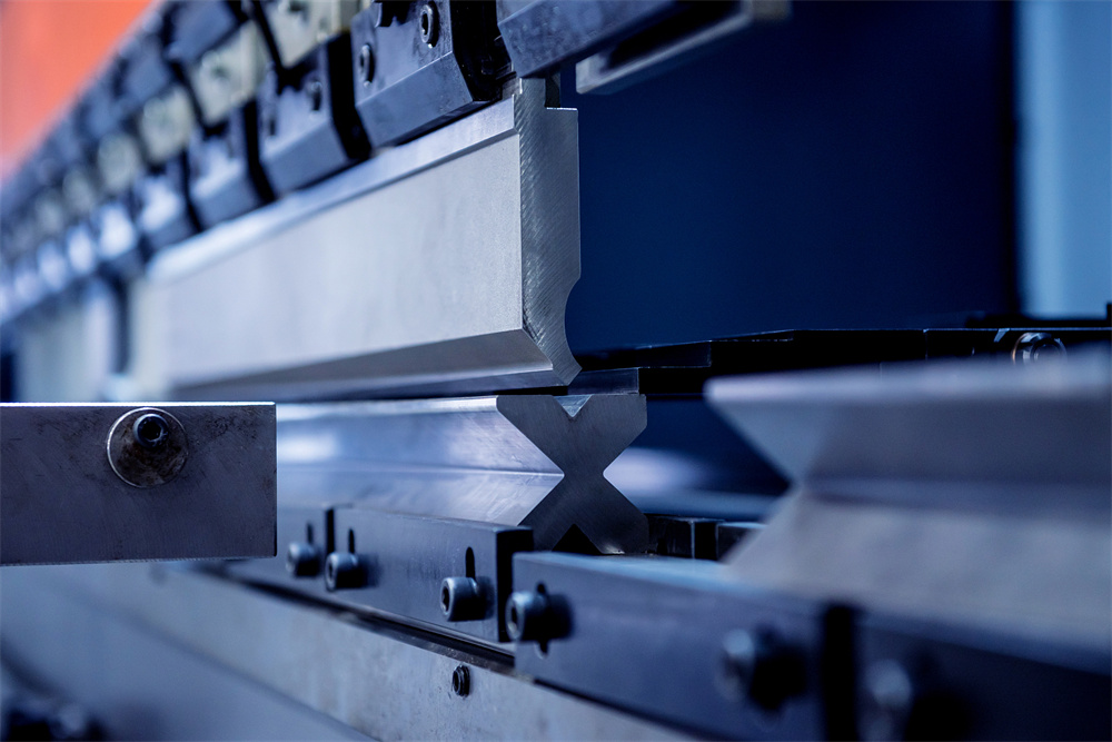
In the world of precision metal fabrication, the accuracy of a finished part is directly proportional to the mechanical integrity of the machine used to create it. Press Brake Alignment: Diagnosing Ram Bed Parallelism Issues is perhaps the most critical aspect of maintaining a high-performance bending operation. Parallelism refers to the constant distance between the upper ram and the lower bed across the entire length of the machine. When this relationship is compromised, even by a fraction of a millimeter, the resulting bend angles will vary, leading to scrapped parts and increased production costs.
Modern hydraulic press brakes, such as those manufactured by HARSLE, utilize sophisticated Y1 and Y2 axis control systems to maintain parallelism. These axes are controlled by independent hydraulic cylinders and monitored by high-precision linear encoders. However, mechanical wear, structural stress, and improper operation can lead to deviations. Diagnosing these issues requires a deep understanding of how the ram interacts with the bed under load. The ram must not only be parallel when stationary but must also maintain that parallelism throughout the entire stroke, especially at the point of maximum pressure.
Parallelism issues often manifest as a ‘twist’ in the ram or a ‘bow’ in the bed. A twist occurs when one end of the ram travels further than the other, usually due to a synchronization error or a leak in one of the hydraulic circuits. A bow, often referred to as deflection, occurs when the center of the bed or ram deforms under high tonnage. While crowning systems are designed to compensate for deflection, they cannot fix fundamental parallelism errors. Therefore, a systematic approach to Press Brake Alignment: Diagnosing Ram Bed Parallelism Issues is essential for any facility aiming for ISO-level quality standards.
The structural design of the press brake also plays a significant role. C-frame machines are inherently prone to ‘throat expansion’ under heavy loads, which can mimic parallelism issues. O-frame machines offer better rigidity but are less common for general-purpose bending. Regardless of the frame type, the guiding system—the ways or gibs that the ram slides on—must be perfectly lubricated and adjusted. If the gibs are too loose, the ram can tilt; if they are too tight, they can cause friction-induced heat, leading to thermal expansion and subsequent alignment drift.
Core Parameters Influencing Parallelism
To effectively address Press Brake Alignment: Diagnosing Ram Bed Parallelism Issues, one must understand the core parameters that govern the machine’s movement. The first is the Stroke Length. The stroke must be perfectly synchronized between the left (Y1) and right (Y2) cylinders. Linear encoders, usually mounted on ‘C’ frames separate from the main side frames to avoid deflection interference, provide real-time feedback to the CNC controller. If the feedback loop is interrupted or if an encoder is misaligned, the ram will lose parallelism.
The second parameter is Tonnage Distribution. Press brakes are designed to handle loads distributed across the bed. When a machine is used for ‘off-center loading’—bending a small, high-tonnage part at one end of the machine—it creates an asymmetrical load. This can lead to permanent deformation of the frame or uneven wear on the guiding system. Over time, this results in a chronic parallelism issue where the ram no longer sits level even when the CNC indicates it is.
Another vital parameter is the Crowning Value. Crowning systems (either hydraulic or mechanical) are integrated into the bed to counteract the natural deflection that occurs when the ram pushes down. If the crowning system is incorrectly calibrated, it can appear as a parallelism issue. For instance, if the center of the bend is over-bent compared to the ends, it might be mistaken for a ram tilt, when in fact it is an over-active crowning system. Distinguishing between these two is a hallmark of expert machine diagnosis.
Calculation Method for Parallelism Diagnosis
Diagnosing parallelism requires precise measurement rather than visual estimation. The most common method involves using a high-precision dial indicator. To begin, the machine should be cleared of all tooling. The bed and ram surfaces must be cleaned thoroughly to remove any debris or oil that could skew the readings. The following steps outline the standard calculation and measurement procedure:
- Step 1: Zeroing the Indicator. Place a dial indicator on the bed at the far left end (near the Y1 cylinder). Lower the ram slowly until it makes contact with the indicator. Set the indicator to zero at a specific CNC position (e.g., Y = 100.00mm).
- Step 2: Measuring the Opposite End. Move the indicator to the far right end (near the Y2 cylinder) without changing the CNC position. Lower the ram to the same Y-position. The reading on the dial indicator represents the parallelism deviation.
- Step 3: Center Point Check. Repeat the process at the center of the bed. If the ends are at zero but the center shows a deviation, the issue is likely bed deflection or a crowning calibration error rather than a ram tilt.
The calculation for adjustment is straightforward: Adjustment = (Reading Y1 – Reading Y2). If the Y1 side is 0.05mm lower than the Y2 side, the CNC parameters for the Y1 axis must be offset by +0.05mm, or the mechanical leveling screws (on older machines) must be adjusted accordingly. In modern CNC systems, this is often handled through the ‘Reference Point’ or ‘Axis Offset’ settings in the controller software.
Parameter Table: Allowable Parallelism Tolerances
The following table provides a general guideline for allowable parallelism deviations based on machine size and the required precision of the work. Note that high-precision aerospace work requires much tighter tolerances than general construction fabrication.
table border=”1″ style=”width:100%; border-collapse: collapse;”>
It is important to remember that these values are for the machine in a static, no-load state. Under load, the deflection compensation system should ideally keep the deviation within the same range. If the deviation increases significantly under load, it indicates a failure in the hydraulic synchronization or the crowning mechanism.
Common Engineering Mistakes in Alignment
One of the most frequent mistakes in Press Brake Alignment: Diagnosing Ram Bed Parallelism Issues is neglecting the Leveling of the Machine Foundation. A press brake is a massive piece of equipment that exerts immense force. If the floor beneath the machine is not perfectly level or if the foundation is settling, the frame of the machine can twist. This ‘frame twist’ makes it impossible to achieve true parallelism between the ram and the bed, as the entire geometry of the machine is skewed. Engineers often try to compensate for this via software, but this is a temporary fix that leads to accelerated wear on the guides.
Another common error is Improper Tool Seating. Sometimes, the ram and bed are perfectly parallel, but the tooling (punches and dies) is not seated correctly. If a small piece of metal scale or a burr is trapped between the punch and the ram, the punch will sit at a slight angle. This creates the illusion of a parallelism issue. Always ensure that the clamping surfaces are pristine before performing an alignment check. Furthermore, using ‘mixed and matched’ tooling from different manufacturers can lead to height variations that mimic alignment problems.
Neglecting Thermal Expansion is a subtle but impactful mistake. In shops without climate control, a press brake can undergo significant temperature changes from morning to afternoon. The hydraulic oil thins, and the metal frame expands. A machine aligned at 6:00 AM may show a parallelism error by 2:00 PM. High-end machines like HARSLE models often include temperature compensation, but for standard models, it is vital to perform critical bends only after the machine has reached a stable operating temperature.
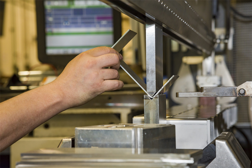
Finally, many operators fail to distinguish between Parallelism and Perpendicularity. Parallelism is the ram being level with the bed. Perpendicularity is the ram moving perfectly vertically relative to the bed. If the ram is tilted forward or backward (pitch), it will cause the punch to enter the die off-center, leading to ‘flange walk’ and uneven angles. Diagnosing parallelism issues must always be done in conjunction with a check of the ram’s vertical travel path.
Selection Checklist for Ensuring Long-Term Alignment
When purchasing a new press brake, certain features can make the task of Press Brake Alignment: Diagnosing Ram Bed Parallelism Issues much easier and less frequent. Use this checklist during your procurement process:
- Frame Rigidity: Look for heavy-duty, stress-relieved steel frames. A heavier frame generally resists deflection better, maintaining parallelism over years of use.
- Linear Encoder Quality: Ensure the machine uses high-resolution encoders (e.g., Heidenhain or Givi Misure) with a mounting system that isolates them from frame deflection.
- Crowning System: Prefer automatic CNC-controlled crowning (either hydraulic or mechanical) over manual systems. This ensures the machine adjusts for parallelism in real-time based on the load.
- Guiding System: Check for wide, hardened, and ground guiding ways. The more surface area the ram has for support, the less likely it is to develop a twist.
- Hydraulic Synchronization: Verify that the machine uses a dual-proportional valve system for Y1 and Y2 control, which offers the highest level of synchronization accuracy.
- Ease of Calibration: Ask the manufacturer how the parallelism is adjusted. Is it a simple software parameter, or does it require mechanical shimming? Software-based adjustment is preferred for modern operations.
Frequently Asked Questions (FAQ)
Q: How often should I check the parallelism of my press brake?
A: For high-production environments, a quick check with a dial indicator should be performed monthly. A full calibration should be done annually or whenever the machine is moved or undergoes major hydraulic service.
Q: Can I fix a parallelism issue by shimming the tools?
A: While shimming can provide a temporary fix for a specific job, it is not a solution for a machine alignment issue. Shimming masks the underlying problem and can lead to uneven wear on the ram and bed surfaces.
Q: What causes the ram to lose parallelism suddenly?
A: Sudden loss of parallelism is usually due to a hydraulic component failure, such as a blown seal in one cylinder, a sticking proportional valve, or a failed linear encoder. It can also happen if the machine hits a hard stop or experiences a severe ‘crash’.
Q: Does the type of hydraulic oil affect alignment?
A: Indirectly, yes. Contaminated or incorrect oil can cause the proportional valves to behave inconsistently, leading to synchronization errors between the Y1 and Y2 axes. Always use the oil grade recommended by the manufacturer.
Q: Is mechanical crowning better than hydraulic crowning for maintaining parallelism?
A: Both have pros and cons. Mechanical crowning (using wedges) is often more stable over long periods and less affected by temperature. Hydraulic crowning is faster and more easily integrated into the CNC’s real-time feedback loop. For most precision applications, CNC-controlled mechanical crowning is highly regarded.
By following this guide to Press Brake Alignment: Diagnosing Ram Bed Parallelism Issues, fabricators can ensure their HARSLE machinery operates at peak performance, delivering consistent, high-quality results for every project. Regular maintenance and a proactive approach to diagnosis are the keys to longevity in the metalworking industry.


