Anatomy of a Press Brake: Exploring the Bed, Ram, and Backgauge

Anatomy of a Press Brake is fundamental to understanding how modern sheet metal fabrication achieves both precision and efficiency. While the bending process may appear straightforward—where a punch presses material into a die—the reality is far more complex. For engineers and production managers, producing accurate bends, especially on long and high-strength sheets, requires a precise balance of mechanical force and advanced control systems. The key components—the bed, ram, and backgauge—must work in perfect synchronization. Their structural stability and coordinated movement directly influence bending accuracy, repeatability, and overall production performance in industrial applications.
Understanding the Basics of Press Brake Anatomy
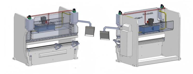
At its core, a press brake is a machine tool used to bend sheet and plate metal with precision. Its structure typically features a rigid frame, such as a C-frame or O-frame design, supporting key components. The bed holds the lower die, while the ram moves vertically to apply force through the punch. Behind them, the backgauge positions the workpiece accurately for consistent bends. In older machines, these parts were driven by mechanical systems like flywheels. Today, modern CNC press brakes use hydraulic or servo-electric systems to control movement with high precision and repeatability, ensuring efficient and accurate bending operations.
The precision of a finished part is never better than the structural rigidity and positional repeatability of the press brake’s core components.
Why the Anatomy of a Press Brake Matters in Modern Fabrication
In high-precision industries like aerospace and medical device manufacturing, the anatomy of a press brake plays a crucial role in product quality. Misalignment of the bed and ram or excessive deflection under load can cause “boating,” where the center of the bend differs from the ends. Similarly, an inaccurate backgauge leads to inconsistent flange lengths, affecting assembly. Understanding these components helps engineers improve bending accuracy and select the appropriate crowning systems to compensate for material behavior. As Industry 4.0 advances, integrating sensors into the ram and backgauge provides real-time adjustments based on material variations, enhancing precision and efficiency.
Key Technical Factors in the Anatomy of a Press Brake
The performance of a press brake is defined by key technical parameters. For the bed and ram, deflection resistance is critical, with crowning systems ensuring accurate bending by compensating for flex under pressure. The ram’s parallelism is maintained by independent hydraulic cylinders (Y1 and Y2 axes) monitored by linear encoders, ensuring precise leveling. The backgauge’s complexity is determined by its axes (X, R, Z1, Z2, X1, X2), affecting part handling. Speed and acceleration of the backgauge are also crucial, as they influence cycle time and overall production efficiency. These components work together to ensure the press brake operates with high precision and reliability.

Technical Calculations for Press Brake Operation
To understand the forces in a press brake, we use the bending tonnage formula: P = (1.42 * TS * s^2 * L) / V. Here, P is the required tonnage, TS is the material’s tensile strength (kg/mm²), s is sheet thickness (mm), L is bending length (m), and V is the die opening (mm). For example, bending 4mm thick mild steel (TS = 45 kg/mm²) over 2 meters with a 32mm V-die gives P = (1.42 * 45 * 16 * 2) / 32, resulting in 63.9 tons of force. This tonnage must not exceed the press brake’s capacity to avoid damaging the bed or ram.
| Axis Designation | Direction of Movement | Function in Fabrication |
|---|---|---|
| Y1 / Y2 | Vertical (Up/Down) | Controls the ram stroke and bending angle accuracy. |
| X | Horizontal (Front/Back) | Determines the flange length of the bent part. |
| R | Vertical (Up/Down) | Adjusts the height of the backgauge fingers for different die heights. |
| Z1 / Z2 | Lateral (Left/Right) | Positions the gauge fingers along the length of the machine. |
| X1 / X2 | Independent Horizontal | Allows for tapered bends and asymmetrical parts. |
Comparing Machine Frame and Drive Technologies
The structural anatomy of a press brake differs based on drive technology. Hydraulic press brakes are traditional and ideal for high-tonnage applications, using fluid power to drive the ram, offering great force but higher maintenance and energy consumption. Servo-Electric press brakes, on the other hand, use high-torque motors and ball screws or belt-drive systems, providing faster operation, better energy efficiency, and higher precision, but are typically limited to lower tonnage (under 150 tons). The frame design also impacts performance: C-frame machines offer deeper flanges but are prone to “yawing,” while O-frame machines provide greater rigidity, minimizing deflection for precise, heavy-duty work.
While hydraulics provide the raw power, it is the electronic synchronization of the Y1 and Y2 axes that provides the finesse required for modern tolerances.
Step-by-Step Guide to Component Inspection and Maintenance
Maintaining a press brake is crucial for long-term performance and part accuracy. Start by inspecting the ram gibs for proper lubrication and signs of wear or scoring, which may indicate parallelism issues. Next, check the bed flatness using a precision straight-edge to ensure there’s no compression from high-tonnage bends. Calibrate the backgauge by verifying the X-axis position with a caliper, ensuring alignment with the V-die. Regularly check the hydraulic oil for contamination and verify the cooling system’s operation, as heat affects oil viscosity and ram precision. Lastly, inspect the crowning system to ensure the compensation curve matches ram deflection under load.
Humanize 106 words
Common Mistakes in Press Brake Operation and Procurement

One common mistake made by factory owners is underestimating the importance of backgauge complexity. Choosing a 2-axis backgauge for handling complex, multi-bend parts often leads to higher labor costs and increased scrap rates. Another issue is center-loading the machine, where operators repeatedly perform short bends in the center, causing localized wear and deflection. Engineers recommend staggering the workspace to distribute the load. Additionally, many buyers overlook the deflection per foot rating of the bed and ram. A machine with a long bed might deflect too much at the center, affecting precision without an active crowning system. Lastly, ignoring material springback in the ram stroke calculation can cause inconsistent angles, especially with stainless steel or high-strength alloys.
Industry Applications of Advanced Press Brake Components
The anatomy of a press brake is customized to suit specific industry needs. In the automotive sector, high-speed servo-electric rams are ideal for quickly producing small brackets and interior components. The heavy equipment industry requires robust hydraulic press brakes with reinforced beds and multi-cylinder rams to handle plates over 25mm thick. In aerospace, 6-axis or 8-axis backgauge systems are crucial for positioning complex fuselage skins and structural ribs. For the HVAC sector, long-bed machines with specialized crowning ensure the creation of ductwork, where maintaining straightness is essential for airtight seals. In each application, the press brake’s structure supports specialized tooling and CNC software tailored to the unique challenges of the material and design.
Conclusion
The anatomy of a press brake—the bed, ram, and backgauge—defines the boundaries and potential of sheet metal fabrication. For mechanical engineers, these components represent key variables in a complex equation of force, friction, and geometry. Choosing a machine with a rigid bed, synchronized and well-guided ram, and a versatile backgauge is crucial for achieving manufacturing excellence. Understanding technical aspects like tonnage calculations and axis movements enables professionals to improve part quality, reduce waste, and extend the equipment’s lifespan. As technology advances, these three elements will integrate more seamlessly, leading to the development of autonomous bending cells and higher precision in the metalworking industry.
FAQ
What is the primary function of crowning in the press brake bed?
Crowning compensates for the natural deflection of the bed and ram that occurs under high tonnage. By slightly arching the center of the bed upward, it ensures a consistent bending angle across the entire length of the workpiece.
How do Y1 and Y2 axes differ from a single-ram control?
In older machines, the ram was driven by a single point or a mechanical link. Y1 and Y2 are independent hydraulic cylinders on either side of the ram, controlled by the CNC to ensure the ram stays perfectly level even with off-center loading.
Why is the R-axis important in a backgauge system?
The R-axis controls the vertical height of the backgauge fingers. This is critical when using different die heights or when a part has a previously bent flange that would otherwise collide with the gauge if it could not move up or down.
Can a press brake bed be permanently damaged by exceeding tonnage?
Yes, exceeding the concentrated load limit (tons per meter) can cause plastic deformation or “upsetting” of the bed and ram surfaces, leading to permanent inaccuracies that require professional machining to repair.
What is the advantage of a servo-electric ram over a hydraulic one?
Servo-electric rams offer higher positioning speeds, better repeatability (often within 0.001mm), lower noise, and significantly reduced energy consumption since they only use power when the ram is moving.


