Press Brake and Metal Bending Terms: The Ultimate Glossary

Press Brake and Metal Bending Terms are essential for precision in sheet metal fabrication. In complex bending operations, a single misunderstanding of technical specifications can result in material waste, damaged tooling, or structural failure. For engineers, factory managers, and procurement specialists, mastering these terms goes beyond theory—it is a practical necessity for efficient production. This guide explores the terminology that underpins modern press brake operations, connecting design intent with shop-floor execution. Standardizing language across the production process ensures tighter tolerances, improved safety, and higher throughput. By understanding and applying these terms consistently, manufacturers can optimize their metal forming workflows and maintain quality across every bending operation.
Understanding the Basics
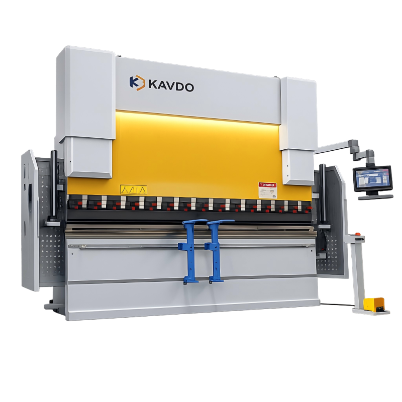
A press brake is a precision machine tool used to create specific bends by clamping a workpiece between a matching punch and die. The machine applies force to a flat sheet, forming a predetermined angle or shape. Its main components are the ram—the moving upper beam—and the bed, the stationary lower beam. Understanding press brake and metal bending terms begins with these elements and their interaction. Modern CNC systems control multiple axes, enabling complex, multi-bend parts with high repeatability. The bending process relies on plastic deformation, where the material is stressed beyond its yield point but remains below its ultimate tensile strength, ensuring the shape holds once the load is removed.
Why This Topic Matters in Sheet Metal Fabrication
In technical environments, precise communication is as critical as machine calibration. When a designer specifies a bending radius, the operator must know whether it refers to the inside radius, outside radius, or tool radius. Misunderstanding press brake and metal bending terms can produce parts that fail to fit their assemblies. With Industry 4.0, simulation and digital twin software rely on accurate parameter input for successful physical parts. Standardized terminology ensures that CAD intent is fully captured in the CNC program, minimizing trial-and-error adjustments on the shop floor. For purchasing managers, familiarity with these terms is vital when defining machine specifications or evaluating tooling options from different suppliers.
In metal fabrication, the language we use is the blueprint for the precision we achieve. A shared vocabulary is the only way to eliminate the gap between engineering intent and manufacturing reality.
Key Factors to Consider
When analyzing bending operations, several technical factors must be evaluated to ensure process stability:
- Material Ductility: The ability of the metal to undergo plastic deformation without fracturing. This is a primary consideration when choosing a bend radius.
- Grain Direction: The orientation of the metal crystals resulting from the rolling process. Bending across the grain is typically preferred to prevent cracking.
- Tonnage Capacity: The maximum force the press brake can exert. Exceeding this limit can cause permanent deflection in the machine frame, often called “ram upset.”
- Tooling Compatibility: Ensuring the punch and die are rated for the required tonnage and that the V-opening is appropriate for the material thickness.
- Springback: The elastic recovery of the material after the bending force is released, which requires the machine to “over-bend” the part to achieve the desired final angle.
Technical Explanation and Calculations
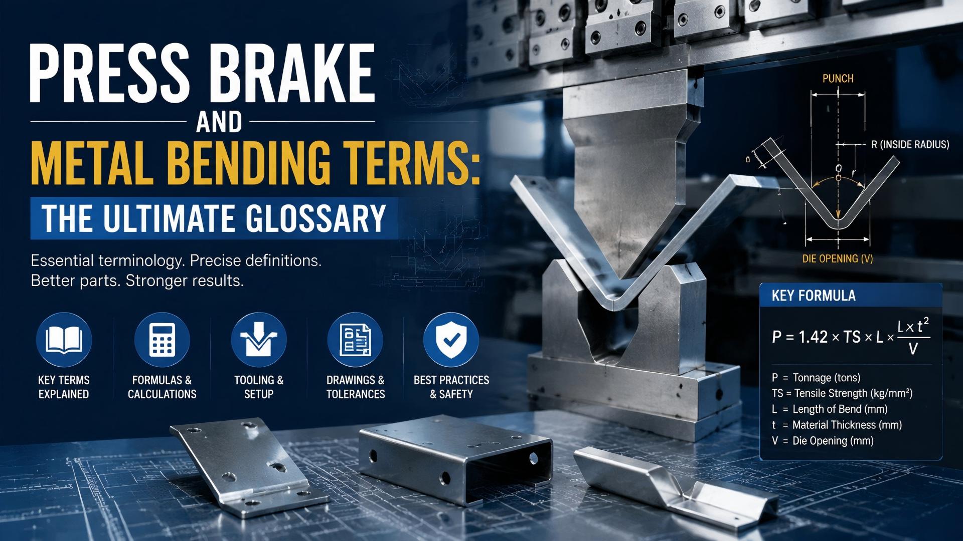
A key aspect of press brake and metal bending terms is the calculation of force and geometry. The most important calculation is Tonnage (P), which determines whether a machine can perform a specific bend. For air bending mild steel, the standard formula is P = (1.42 × TS × L × t²) / V, where P is the press force in tons, TS is the material’s tensile strength (around 45 kg/mm² for mild steel), L is the bend length in millimeters, t is material thickness, and V is the V-die opening. This equation shows that required force grows exponentially with sheet thickness and decreases as die opening increases, highlighting the importance of precise calculations in press brake operations.
Another essential calculation involves determining the flat blank length, which requires understanding the Bending Allowance (BA) and the K-Factor. The K-Factor is the ratio of the neutral axis position to the material thickness. The formula for Bending Allowance is: BA = (pi / 180) * A * (R + K * t), where A is the bend angle in degrees and R is the inside bend radius. These calculations ensure that the flat piece of metal, once bent, will match the final dimensions required by the engineering drawing.
Comparison of Bending Methods
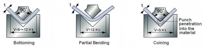
Understanding the differences between bending methods is crucial for selecting the right process for a specific application. The table below compares the three primary types of bending.
| Method | Precision | Tonnage Requirement | Flexibility |
|---|---|---|---|
| Air Bending | Moderate | Low | High (Multiple angles with one tool) |
| Bottoming | High | Medium-High | Low (Specific tool for specific angle) |
| Coining | Very High | Extreme | Very Low (Permanent deformation) |
Air bending is the most common method in modern fabrication because the punch tip does not need to force the material into the bottom of the die. This allows for various angles to be achieved by simply adjusting the depth of the punch stroke. Bottoming and coining, while providing higher precision and less springback, require significantly more force and specialized tooling for every unique angle and thickness.
Detailed Glossary of Press Brake and Metal Bending Terms
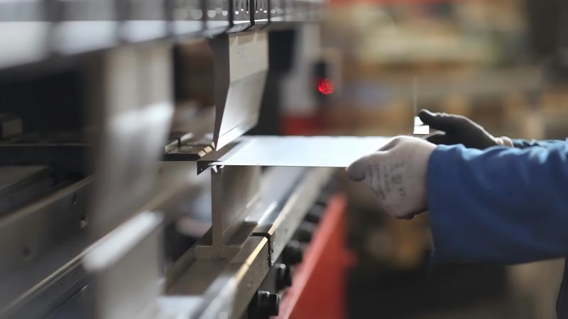
To provide a comprehensive resource, we have categorized the most essential terms into three functional groups: Machine Components, Tooling, and Geometry.
Machine and Operational Terms
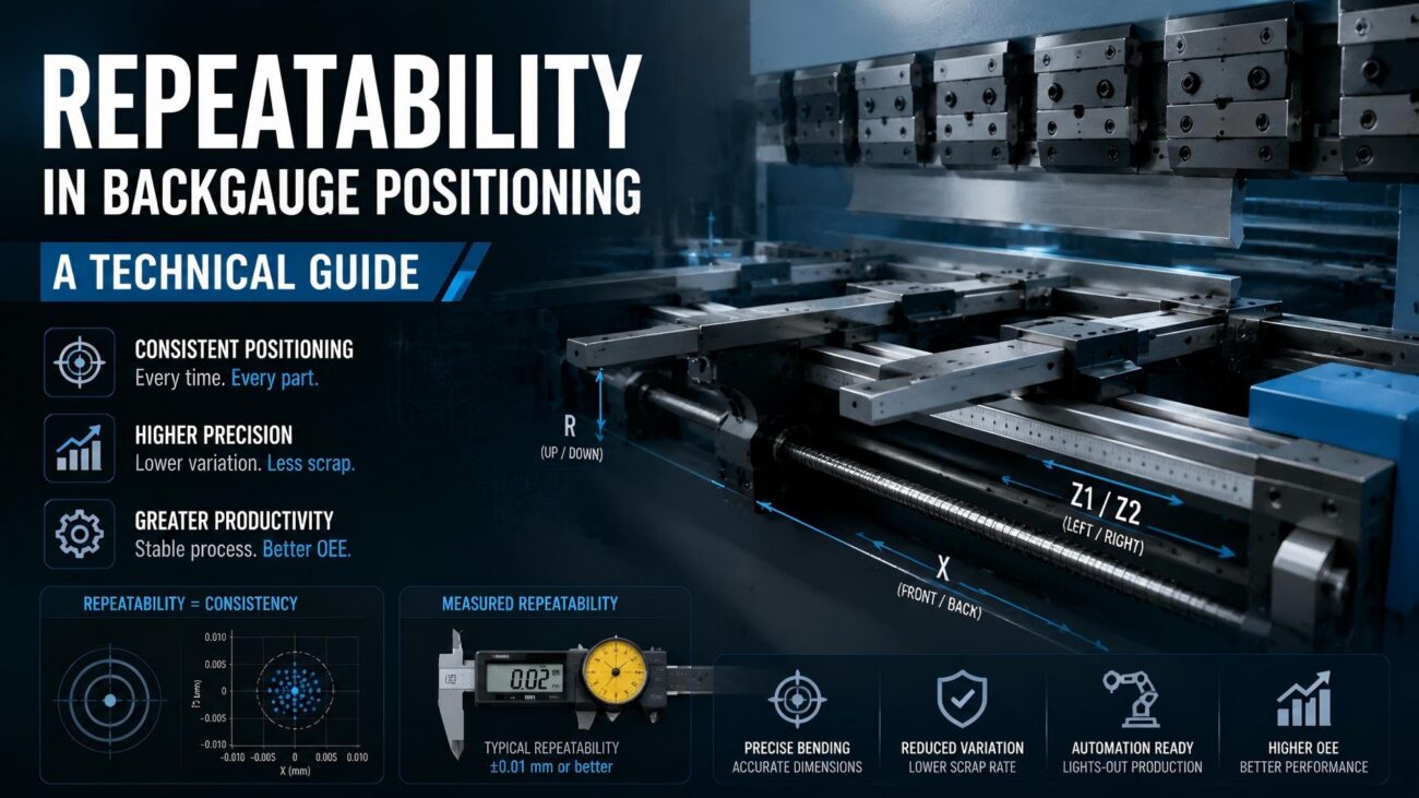
- Backgauge: A motorized system of stops that moves along multiple axes (X, R, Z) to position the workpiece accurately before the bend occurs.
- Crowning: A compensation method used to counteract the natural deflection of the ram and bed under load. It ensures a consistent angle across the entire length of a long part.
- Y1/Y2 Axes: The independent control of the two hydraulic cylinders at either end of the ram, allowing for precise leveling and angle control.
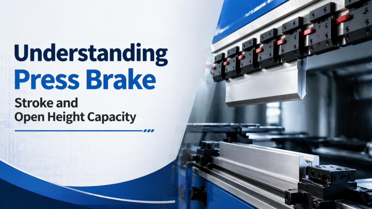
- Stroke: The total vertical distance the ram can travel from its top position to its bottom limit.
- Throat Depth: The distance from the center of the tools to the back frame of the machine, which limits the size of the flange that can be bent.
Tooling and Material Terms
- Gooseneck Punch: A specialized punch with a deep relief area designed to clear previously formed flanges during complex bending sequences.
- V-Die Opening: The width of the opening in the lower tool. A general rule is to use a V-opening 8 times the material thickness (8t).
- Tensile Strength: The maximum stress a material can withstand while being stretched or pulled before necking.
- Yield Strength: The stress level at which a material begins to deform plastically and will no longer return to its original shape.
- Work Hardening: The increase in hardness and strength of a metal resulting from plastic deformation during the bending process.
Geometry and Calculation Terms
- Inside Bend Radius: The radius of the inner surface of the bend. In air bending, this is typically 15 to 20 percent of the V-die opening.
- Neutral Axis: The theoretical plane within the sheet metal that remains at its original length during a bend, neither stretching nor compressing.
- Bending Deduction (BD): The amount of material that must be subtracted from the sum of the flange lengths to determine the correct flat blank length.
- Hemming: A two-stage process where a sheet is bent to an acute angle and then flattened to create a finished, safe edge.
- Offset Bending: A process that creates two bends simultaneously to produce a Z-shaped profile in the metal.
Step-by-Step Guide to Selecting Bending Parameters
Identify Material Specifications: Determine sheet thickness, tensile strength, and grain direction, as these are key inputs for all calculations. Calculate Required Tonnage: Apply the tonnage formula to confirm the machine can bend the part safely, including a 20 % safety margin. Select Tooling: Choose a V-die opening based on the 8t rule for mild steel and pick a punch radius close to the desired inside bend radius without exceeding the minimum allowable radius. Determine Blank Development: Use the K-factor and bending deduction to calculate the precise flat sheet dimensions required before bending. Set Crowning and Compensation: For parts longer than one meter, account for deflection and adjust the crowning system to maintain consistent bend angles.
Common Mistakes to Avoid
One of the most frequent errors in sheet metal fabrication is neglecting the impact of springback. Engineers often design parts with 90-degree angles without considering that the material will naturally open up by 1 to 5 degrees once released. Another critical mistake is using a V-die opening that is too small for the material thickness. This not only increases the required tonnage exponentially, potentially damaging the machine, but also risks cracking the material on the outside of the bend. Finally, failing to account for grain direction can lead to inconsistent results and structural weakness, especially in high-strength aluminum or stainless steel alloys.
Precision is not an accident; it is the result of rigorous adherence to technical principles and a clear understanding of the forces at play within the material.
Industry Applications
The mastery of **press brake and metal bending terms** is applied across a vast array of industries. In the aerospace sector, where weight and strength are paramount, precision bending of titanium and high-strength alloys is essential for structural components. In the automotive industry, complex panel benders and press brakes create the intricate frames and safety cages that protect passengers. The HVAC industry relies on high-speed bending for ductwork and housing components, where consistent flange lengths are critical for assembly. In each of these fields, the technical vocabulary provided in this glossary serves as the primary tool for maintaining quality and efficiency.
Conclusion
Navigating the complexities of sheet metal fabrication requires a robust technical foundation. By fully understanding **press brake and metal bending terms**, professionals can bridge the gap between theoretical design and physical production. Whether it is calculating the precise tonnage for a high-strength alloy or selecting the correct crowning values for a three-meter workpiece, these terms represent the core knowledge required for modern manufacturing excellence. As you continue to optimize your fabrication processes, prioritize the use of standardized terminology and rigorous mathematical validation to ensure that every bend meets the highest standards of precision and reliability.
FAQ
What is the difference between air bending and bottoming?
Air bending contacts the material at only three points and does not force the sheet to the bottom of the die, allowing for variable angles. Bottoming forces the sheet into full contact with the die, requiring higher tonnage but providing more consistent angles with less springback.
How is the K-Factor determined in metal bending?
The K-Factor is a ratio representing the location of the neutral axis within the material thickness. It is typically determined through empirical testing or standard material charts, with a common default value of 0.448 for mild steel air bending.
Why is the 8t rule used for selecting V-die openings?
The 8t rule (V-opening = 8 times material thickness) provides an optimal balance between the required tonnage and the resulting inside bend radius for mild steel. It prevents excessive force on the machine while ensuring a stable and repeatable bend.
What causes ram upset in a press brake?
Ram upset occurs when the central portion of the ram or bed is permanently deflected due to excessive tonnage concentrated in a small area. This results in a permanent “bow” in the machine, making it impossible to achieve straight bends without significant repair.
How can springback be effectively managed?
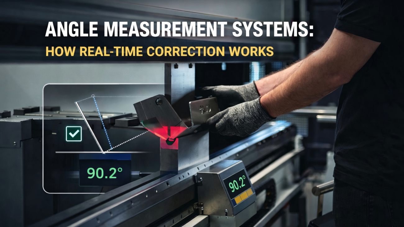
Springback is managed by over-bending the part beyond the target angle, using CNC controllers with integrated angle-sensing systems that provide real-time feedback and automatic compensation during the stroke.