How to Increase Bending Accuracy with a Press Brake Crowning System

Technical Overview: The Physics of Deflection and Crowning
In the world of precision metal fabrication, achieving a perfectly uniform bend across the entire length of a workpiece is one of the most significant challenges. When a press brake applies several hundred tons of force to a sheet of metal, the machine itself is subject to the laws of physics—specifically, Newton’s Third Law. As the ram pushes down on the workpiece and the die, an equal and opposite force pushes back against the ram and the bed. This results in a phenomenon known as ‘deflection.’
Deflection causes the ram to bow upward in the center and the bed to bow downward. Because the center of the machine is the furthest point from the side frames (the housings), it is the most flexible area. Consequently, the punch does not penetrate the die as deeply in the middle as it does near the ends. This leads to the ‘canoe effect,’ where the bend angle in the center of the part is wider (more obtuse) than the angles at the ends. To increase bending accuracy a press brake crowning system is employed to counteract this physical deformation.
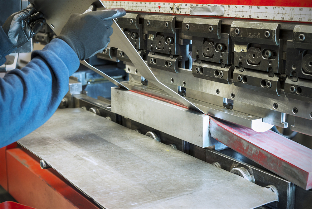
A crowning system essentially introduces a controlled curve into the bed or the ram that mirrors the predicted deflection. By ‘crowning’ the bed upward, the machine ensures that the distance between the punch and the die remains constant across the entire length of the machine, even under full load. This technology is essential for any shop producing long parts or working with high-tensile materials where even a fraction of a millimeter of deflection can result in a rejected part.
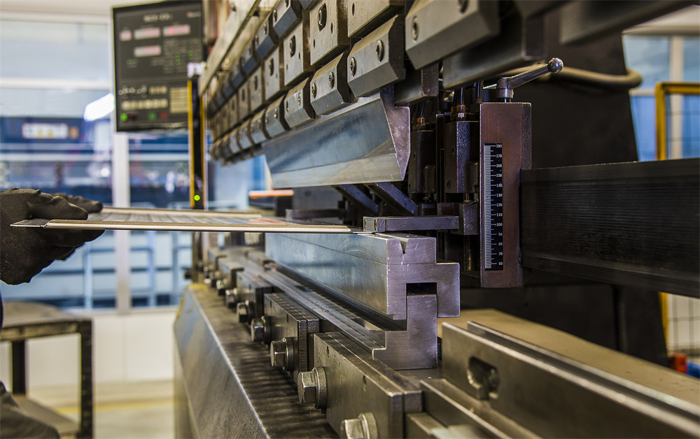
Modern crowning systems are categorized into two primary types: Hydraulic and Mechanical. Hydraulic crowning uses a series of cylinders located within the lower bed that expand under pressure to push the bed upward. Mechanical crowning, often preferred for its precision and stability, uses a series of sliding wedges (often called ‘Wila-style’ or ‘Wave-style’) that are adjusted via a motor or manual crank to create a precise compensation curve. Understanding these systems is the first step to mastering how to increase bending accuracy a press brake crowning system.
Core Parameters Influencing Bending Accuracy
To effectively increase bending accuracy a press brake crowning system must be tuned to the specific variables of the job. Several core parameters dictate how much compensation is required. The most prominent factor is the material’s tensile strength. Stainless steel, for instance, requires significantly more pressure to bend than aluminum, leading to higher deflection and a greater need for crowning adjustment.
The length of the workpiece is another critical parameter. Deflection is not linear; it increases exponentially with the length of the bed being utilized. A 4-meter press brake will experience significantly more ‘bowing’ than a 2-meter machine when subjected to the same tonnage per meter. Therefore, the crowning system must be capable of providing a variable curve that matches the specific length of the part being processed.
Tonnage is the third pillar of crowning parameters. The total force required to air-bend a piece of metal depends on the material thickness and the V-opening of the die. As tonnage increases, the structural components of the press brake (the side frames, ram, and bed) undergo greater elastic deformation. A sophisticated CNC crowning system calculates this tonnage in real-time and adjusts the crowning wedges or hydraulic pressure before the stroke is completed.
Finally, the ‘Y-axis’ precision and the machine’s structural integrity play a role. If the press brake’s frame is not rigid enough, or if the Y1 and Y2 cylinders are not perfectly synchronized, even the best crowning system will struggle to maintain accuracy. High-quality manufacturers like HARSLE design their frames with high safety factors to minimize base deflection, making the crowning system’s job more manageable and precise.
Calculation Method for Deflection Compensation
While modern CNC controllers handle most calculations automatically, understanding the underlying math is vital for engineers looking to increase bending accuracy a press brake crowning system. The deflection of a press brake bed can be modeled similarly to a beam supported at two points with a distributed load. The standard formula for maximum deflection (δ) in the center of a beam is:
δ = (5 × P × L³) / (384 × E × I)
- P: The total load or tonnage applied.
- L: The distance between the side frames (housing distance).
- E: The Modulus of Elasticity of the machine’s steel frame.
- I: The Moment of Inertia of the bed or ram cross-section.
In practical application, the crowning system must provide a compensation value (C) that is equal to the sum of the ram deflection and the bed deflection. For a mechanical crowning system, this translates to the vertical displacement of the wedges. For example, if the calculated total deflection is 0.8mm, the CNC controller will signal the crowning motor to move the wedges to a position that raises the center of the die by exactly 0.8mm.
Advanced systems also account for ‘Springback.’ When the pressure is released, the metal naturally tries to return to its original shape. While crowning primarily addresses the physical deflection of the machine, it indirectly assists in managing springback by ensuring the initial ‘over-bend’ is consistent across the entire length. Without accurate crowning, the springback would vary from the center to the ends, making it impossible to achieve a straight part.
Parameter Table: Crowning Requirements by Material and Length
The following table provides a general reference for the required crowning compensation (in millimeters) for various materials and lengths on a standard 100-ton press brake. Note: These values are indicative and will vary based on specific machine rigidity and die selection.
| Material Type | Thickness (mm) | Workpiece Length (m) | Required Tonnage (Est.) | Crowning Comp. (mm) |
|---|---|---|---|---|
| Mild Steel (450MPa) | 2.0 | 2.0 | 30 | 0.15 – 0.25 |
| Mild Steel (450MPa) | 4.0 | 3.0 | 120 | 0.45 – 0.60 |
| Stainless Steel (600MPa) | 2.0 | 2.0 | 45 | 0.30 – 0.40 |
| Stainless Steel (600MPa) | 4.0 | 3.0 | 180 | 0.75 – 0.95 |
| Aluminum (250MPa) | 3.0 | 2.5 | 40 | 0.10 – 0.20 |
| High-Strength Steel (700MPa) | 3.0 | 3.0 | 160 | 0.80 – 1.10 |
As seen in the table, as the tensile strength and length increase, the necessity to increase bending accuracy a press brake crowning system becomes paramount. A failure to adjust for these variables results in the ‘center-wide’ angle error that plagues many fabrication shops.
Common Engineering Mistakes in Crowning Adjustment
One of the most frequent mistakes is ‘Over-Crowning.’ Operators often assume that if a little crowning is good, more is better. However, over-compensating creates the opposite of the canoe effect: the center angle becomes tighter (more acute) than the ends. This not only ruins the part but can also put unnecessary localized stress on the center of the ram and the crowning wedges.
Another common error is ignoring the ‘Grain Direction’ of the sheet metal. Metal is rolled in a specific direction at the mill, and it bends differently depending on whether the bend line is parallel or perpendicular to the grain. While crowning compensates for machine deflection, the operator must still adjust the overall Y-axis depth to account for grain-related resistance. If the crowning is set perfectly for a cross-grain bend but the next part is with-the-grain, the accuracy will still suffer.
Neglecting maintenance of the crowning system is a silent killer of accuracy. In mechanical systems, dust and metal shavings can migrate between the wedges, causing them to stick or move unevenly. In hydraulic systems, air bubbles in the fluid or worn seals can lead to inconsistent pressure. To increase bending accuracy a press brake crowning system must be kept clean and lubricated according to the manufacturer’s specifications.
Finally, many engineers fail to consider the ‘Sweet Spot’ of their machine. Every press brake has a range where it is most accurate. Attempting to bend a very short, thick part in the dead center of a very long machine can sometimes lead to ‘upset’ or localized deformation that the crowning system isn’t designed to handle. In these cases, it is often better to bend off-center (if the machine allows) or use specialized short-bed machines.
Selection Checklist: Choosing the Right Crowning System
When purchasing a new HARSLE press brake or upgrading an existing one, choosing the right crowning system is critical. Use this checklist to ensure you select the system that will best increase bending accuracy a press brake crowning system for your specific needs:
- System Type: Do you require Hydraulic or Mechanical crowning? Mechanical is generally preferred for high-precision CNC applications due to its ‘set-and-forget’ stability.
- CNC Integration: Does the crowning system communicate directly with the controller? Look for ‘Auto-Crowning’ features where the software calculates the curve based on material and thickness.
- Adjustment Points: How many adjustment points (wedges) does the system have? More points allow for a more ‘natural’ and smooth curve, preventing ‘stepping’ in the bend.
- Load Capacity: Is the crowning system rated for the maximum tonnage of the machine? Using a light-duty crowning table on a heavy-duty machine will lead to premature failure.
- Retrofit Compatibility: If you are upgrading an old machine, is the bed designed to accept a crowning table without losing too much ‘Open Height’?
- Ease of Maintenance: Are the wedges or cylinders easily accessible for cleaning and service?
- Accuracy Resolution: Can the system make adjustments in increments of 0.01mm or better?
Frequently Asked Questions (FAQ)
1. Can I add a crowning system to an older press brake?
Yes, many older machines can be retrofitted with a manual or CNC-controlled mechanical crowning table. This is one of the most cost-effective ways to increase bending accuracy a press brake crowning system on an existing machine. However, you must ensure the machine has enough ‘Shut Height’ to accommodate the thickness of the new table.
2. Why is my bend angle still inconsistent even with crowning?
Crowning only addresses machine deflection. Inconsistencies can still arise from variations in material thickness (gauge tolerance), differences in material yield strength between batches, or worn tooling. If the crowning is set correctly, check your material and the condition of your punch and die.
3. Is mechanical crowning better than hydraulic crowning?
Mechanical crowning is generally considered more precise and repeatable because it relies on physical wedges that do not ‘drift’ like hydraulic fluid can. However, hydraulic crowning is often faster to react and is integrated into the machine’s base price more frequently. For high-end precision work, mechanical is the industry standard.
4. How often should I calibrate my crowning system?
For high-production environments, the crowning system should be checked monthly. Perform a ‘test bend’ on a long strip of material and measure the angle at 5-10 points along the length. If the center deviates from the ends, the crowning parameters in the CNC controller may need recalibration.
5. Does crowning help with short parts?
Crowning is primarily designed for parts that span a significant portion of the bed length. For very short parts (e.g., 300mm on a 3000mm bed), the machine deflection is negligible, and the crowning system should typically be set to zero or a very low value.
Conclusion: The ROI of Precision Crowning
Investing in a high-quality crowning system is not just about technical specs; it is about the bottom line. When you increase bending accuracy a press brake crowning system, you significantly reduce scrap rates and eliminate the need for secondary operations like manual straightening or ‘re-hitting’ parts. In industries like aerospace, medical equipment, and high-end architectural metalwork, the ability to hold a +/- 0.5-degree tolerance over a 4-meter bend is a major competitive advantage.
HARSLE press brakes are engineered with these challenges in mind, offering both advanced hydraulic and mechanical crowning solutions that integrate seamlessly with modern CNC controllers. By understanding the physics of deflection, maintaining your equipment, and selecting the right parameters, you can ensure that every bend is as perfect as the first. Accuracy is the hallmark of a professional fabrication shop, and the crowning system is the heart of that accuracy.


