Punching Machine Technical Guide: How It Works, Key Components, and Industrial Applications


Technical Overview of Punching Machine Technology
The punching machine, often referred to as a punching press, is a cornerstone of the metalworking industry. At its most fundamental level, the Punching Machine Technical : It Works, Key Components, Industrial Applications framework revolves around the application of force to a workpiece to create holes, indentations, or specific shapes. This process is achieved by pressing a tool, known as the punch, through the workpiece and into a die. The interaction between the punch and the die results in the shearing of the material, which is the primary mechanism of metal removal in this context.
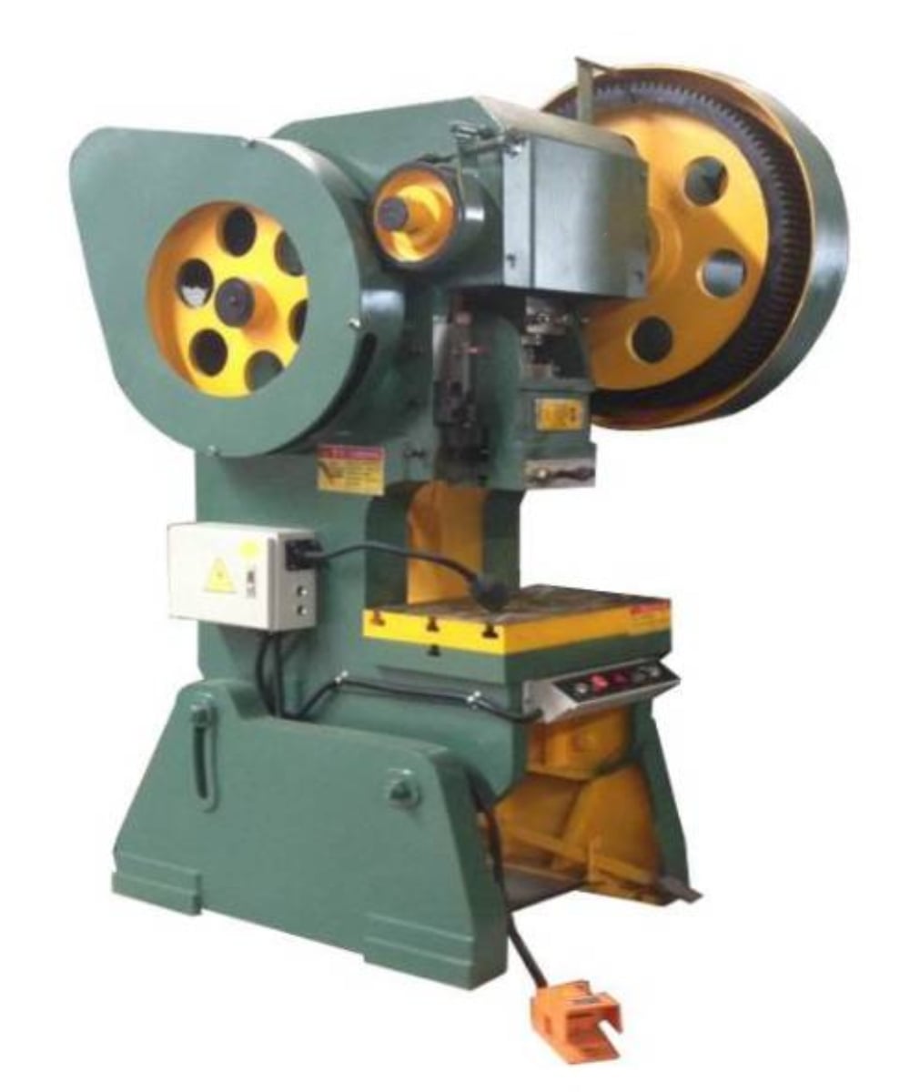
Modern punching machines have evolved significantly from simple mechanical levers to highly sophisticated CNC (Computer Numerical Control) systems. These machines utilize various power sources, including mechanical flywheels, hydraulic cylinders, and servo-motors. In a mechanical punching machine, energy is stored in a heavy rotating flywheel. When the operator engages the clutch, the flywheel’s rotational energy is converted into linear motion via a crankshaft or eccentric shaft, driving the ram downward with immense force. This design is favored for high-speed, high-volume production where consistent stroke depth is required.
Hydraulic punching machines, on the other hand, utilize fluid pressure to move the ram. This allows for full tonnage to be available at any point in the stroke, providing greater flexibility for deep drawing or forming operations that require controlled speed and pressure. HARSLE has integrated these technologies to offer hybrid solutions that combine the speed of mechanical systems with the precision and control of hydraulic systems. Understanding the physics of the shear zone—where the material transitions from elastic deformation to plastic deformation and finally to fracture—is essential for optimizing the punching process.
The Mechanics of the Punching Cycle
The punching cycle consists of several distinct phases: the approach, the penetration, the fracture, and the stripping. During the approach, the ram moves the punch toward the material surface. As the punch contacts the metal, it initially causes elastic deformation. As the pressure increases, the material enters the plastic zone, where it begins to flow into the die opening. This is where the importance of the ‘Punching Machine Technical : It Works, Key Components, Industrial Applications’ knowledge becomes critical, as the clearance between the punch and die determines the quality of the resulting hole.
Once the material’s ultimate shear strength is exceeded, a fracture begins at the cutting edges of both the punch and the die. These fractures meet, and the ‘slug’ (the waste material) is pushed through the die. Finally, the stripping phase occurs as the punch retracts. Because the metal tends to grip the punch due to lateral expansion, a stripper plate is necessary to hold the material down while the punch pulls away. Efficient cycle management is what allows HARSLE machines to achieve hundreds of strokes per minute without compromising structural integrity.
Core Components of a Punching Machine
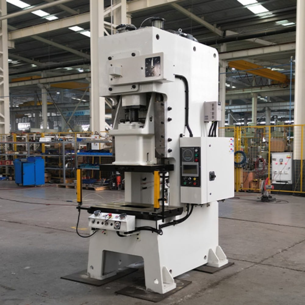
To understand how these machines operate under extreme stress, one must examine the individual components that make up the assembly. The frame is the backbone of the machine, typically constructed in either a C-frame (gap frame) or an H-frame (straight-side) configuration. C-frames offer excellent accessibility for the operator and can accommodate larger sheets of metal, but they are susceptible to ‘angular deflection’ under high loads. H-frames are more rigid and are used for high-precision, high-tonnage applications where maintaining perfect alignment between the punch and die is paramount.
The ram or slide is the moving component that carries the punch. It is guided by precision-machined ‘gibbing’ or slide-ways that ensure vertical accuracy. In high-end HARSLE models, these guides are often lined with wear-resistant materials and feature automatic lubrication systems to minimize friction and heat buildup. The bolster plate sits on the machine bed and provides a flat, stable surface for mounting the die set. It must be thick enough to resist deflection and often features T-slots for secure clamping of the tooling.
The drive system is another critical component. In mechanical presses, this includes the flywheel, clutch, and brake. The clutch engages the flywheel to the crankshaft, while the brake stops the ram’s motion instantly when the clutch is disengaged. Modern safety standards require these systems to be ‘fail-safe,’ meaning any loss of power or air pressure will automatically engage the brake. In CNC turret punch presses, the turret itself is a core component, holding dozens of different tools that can be indexed and selected automatically by the control system, allowing for complex part geometries to be produced in a single setup.
Tooling and Die Sets
The tooling is where the actual work happens. A standard die set consists of the punch, the die, and the stripper. The punch is the male component that matches the desired hole shape, while the die is the female component with a slightly larger opening. The difference in size is known as the ‘die clearance.’ Proper clearance is usually between 5% and 10% of the material thickness. If the clearance is too small, it increases tool wear and requires more force; if it is too large, it results in excessive burrs on the workpiece.
Core Parameters of Punching Machines
When evaluating a punching machine, several technical parameters define its capability and suitability for specific tasks. Tonnage is the most vital parameter, representing the maximum force the machine can exert. This is not just a measure of the motor’s power but a reflection of the frame’s structural strength and the drive system’s torque capacity. Calculating the required tonnage for a specific job is a fundamental engineering task that prevents machine overload and tool breakage.
- Stroke Length: The total distance the ram travels from its highest point to its lowest point. Fixed strokes are common in mechanical presses, while adjustable strokes are found in hydraulic and some high-end servo-mechanical presses.
- Strokes Per Minute (SPM): This indicates the machine’s speed. High-speed punching machines can exceed 600-1000 SPM, making them ideal for mass-producing small components like electrical connectors.
- Shut Height: The distance between the bolster plate and the ram when the ram is at the bottom of its stroke. This determines the maximum height of the die set that can be installed.
- Throat Depth: In C-frame machines, this is the distance from the center of the ram to the back of the frame. It dictates the maximum width of the sheet metal that can be processed.
Calculation Method for Punching Force
To ensure the longevity of your HARSLE equipment, you must accurately calculate the force required for every operation. The standard formula for calculating punching force (P) is based on the perimeter of the cut, the thickness of the material, and its shear strength. The formula is expressed as:
P = L × t × τ
Where:
P = Punching Force (in Newtons or Tons)
L = Total length of the cut perimeter (e.g., π × diameter for a round hole)
t = Material thickness
τ = Shear strength of the material (usually about 70-80% of the tensile strength)
For example, if you are punching a 50mm diameter hole in a 3mm thick mild steel plate with a shear strength of 345 MPa, the calculation would be: Perimeter (157.08mm) × Thickness (3mm) × Shear Strength (345 N/mm²). This results in approximately 162,577 Newtons, or roughly 16.5 tons. It is industry standard to add a 20% safety margin to this figure to account for tool dulling and material variations, meaning a 20-ton press would be the minimum requirement for this specific task.
Punching Machine Parameter Comparison Table
The following table compares the three primary types of punching machines used in modern industrial environments. This comparison helps in understanding which technology aligns best with specific production goals.
| Feature | Mechanical Power Press | Hydraulic Punching Machine | CNC Turret Punch Press |
|---|---|---|---|
| Drive Mechanism | Flywheel & Crankshaft | Hydraulic Cylinder | Servo-Hydraulic / Electric |
| Speed (SPM) | Very High (100-1000+) | Moderate (20-100) | High (300-800) |
| Force Control | Fixed at bottom of stroke | Constant throughout stroke | Programmable & Precise |
| Best For | High-volume simple parts | Deep drawing & heavy plate | Complex shapes & prototyping |
| Tooling Change | Manual / Slow | Manual / Moderate | Automatic / Very Fast |
| Precision | High | Moderate to High | Extremely High |
Industrial Applications of Punching Machines
The versatility of punching machines makes them indispensable across various sectors. In the automotive industry, these machines are used to create structural brackets, body panels, and interior reinforcements. The ability to perform multiple operations—such as punching, louvering, and embossing—in a single cycle makes them highly efficient for automotive assembly lines. High-tonnage H-frame presses are typically used for heavy-duty chassis components, while smaller C-frame presses handle intricate electrical housing parts.
In the electronics and telecommunications sector, CNC turret punch presses are the preferred choice. They are used to manufacture server racks, computer chassis, and shielded enclosures. These parts often require hundreds of small holes for ventilation and complex cutouts for connectors. The precision of HARSLE CNC systems ensures that these components meet the tight tolerances required for high-tech assembly. Furthermore, the aerospace industry utilizes specialized punching machines to process high-strength alloys like titanium and stainless steel, where edge quality and material integrity are paramount.
The construction and HVAC industries also rely heavily on punching technology. From manufacturing ductwork and ventilation grilles to producing heavy-duty gussets for steel buildings, the punching machine provides a cost-effective alternative to laser cutting for high-volume, repetitive shapes. The speed of a mechanical press is unmatched when producing thousands of identical perforated panels or mounting brackets used in infrastructure projects.
Common Engineering Mistakes in Punching Operations
Even with high-quality machinery from HARSLE, engineering errors can lead to poor part quality and machine damage. One of the most common mistakes is improper die clearance. As mentioned earlier, clearance that is too tight leads to ‘secondary shear,’ which creates a ragged edge and doubles the force required, leading to premature tool failure. Conversely, excessive clearance causes a large ‘roll-over’ at the top of the hole and a heavy burr at the bottom.
Another frequent error is ignoring the tonnage curve. In a mechanical press, the rated tonnage is only available near the bottom of the stroke. Attempting to perform a high-force operation (like deep forming) near the top of the stroke can stall the motor or snap the crankshaft because the mechanical advantage of the linkage is at its lowest. Engineers must also be wary of slug pulling, where the waste material sticks to the punch and is pulled back up out of the die. This can cause ‘double-hitting,’ which often results in catastrophic tool breakage and potential damage to the machine’s ram.
Finally, poor lubrication is a silent killer of punching machines. Without proper lubrication of the gibs and the tooling, heat builds up rapidly. This heat causes thermal expansion, which can lead to the ram seizing in the guides or the punch galling (welding itself) to the workpiece. Implementing an automated lubrication schedule and using the correct type of punching oil for the material being processed are essential steps in any professional fabrication shop.
Selection Checklist for Buying a Punching Machine
Choosing the right machine requires a balance between current needs and future growth. Use this checklist to guide your procurement process:
- Material Specifications: What is the maximum thickness and tensile strength of the materials you will process? Ensure the machine tonnage exceeds your highest calculation by at least 20%.
- Part Complexity: Do you need simple round holes or complex geometries? If the latter, a CNC turret punch press with multi-tool capabilities is necessary.
- Production Volume: For millions of parts per year, a high-speed mechanical press is the most economical. For short runs and prototyping, a CNC machine offers better flexibility.
- Accuracy Requirements: Does the application require aerospace-grade tolerances? If so, look for machines with H-frame construction and servo-driven rams.
- Table Size and Throat Depth: Ensure the machine can physically accommodate the largest sheets of metal you plan to use.
- Safety and Compliance: Does the machine meet local safety standards (e.g., CE, OSHA)? Look for light curtains, dual-hand controls, and interlocked guarding.
- After-Sales Support: Does the manufacturer (like HARSLE) provide comprehensive training, spare parts availability, and technical support?
Frequently Asked Questions (FAQ)
1. How often should I sharpen my punching tools?
Tool sharpening frequency depends on the material being punched and the tool coating. A general rule of thumb is to sharpen the punch and die when the ‘radiusing’ of the cutting edge reaches 0.1mm. Punching stainless steel will dull tools much faster than aluminum or mild steel. Regular maintenance prevents the need for removing large amounts of material during sharpening, thus extending the total life of the tool.
2. Can a punching machine be used for forming?
Yes, many punching machines, especially CNC turret presses and hydraulic presses, can perform forming operations such as creating louvers, countersinks, ribs, and small bends. However, these operations require specialized tooling and careful control of the stroke depth to avoid ‘bottoming out’ the tool and damaging the machine.
3. What is the difference between a punching machine and a laser cutter?
Punching machines are significantly faster for creating repetitive holes and can perform forming operations (like louvers) that lasers cannot. However, laser cutters are better for very complex, irregular shapes and do not require expensive custom tooling. For high-volume production of parts with many holes, a punching machine is usually more cost-effective.
4. Why is my punching machine making a loud ‘bang’ during operation?
A loud, sharp noise often indicates ‘breakthrough shock.’ This happens when the material suddenly fractures, and the stored energy in the machine frame is released instantly. This can be mitigated by using ‘sheared’ tooling (where the punch face is ground at an angle) to distribute the cutting force over a longer portion of the stroke, or by using hydraulic shock absorbers.
5. How do I calculate the ‘slug’ clearance for different materials?
The general rule is 5% of material thickness per side (10% total) for mild steel. For harder materials like stainless steel, you may increase this to 15-20% total clearance to reduce tool wear. For very soft materials like aluminum, a tighter clearance (5-8% total) is often used to prevent excessive burring and ‘pulling’ of the material into the die.