Comprehensive Guide: How to Calculate Bend Allowance and Bend Deduction on a Press Brake

Technical Overview of Metal Bending Physics
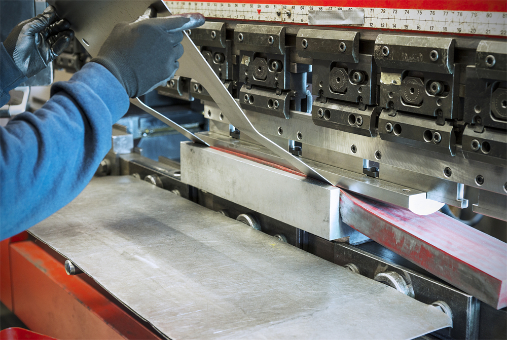
In the world of precision metal fabrication, understanding the physics of a bend is the difference between a perfect part and scrap metal. When a sheet of metal is bent using a press brake, the material undergoes physical changes: the inner surface of the bend is compressed, while the outer surface is stretched. Somewhere between these two extremes lies a theoretical line known as the neutral axis, where the material length remains unchanged. To accurately determine the flat length of a part before it is bent, engineers must master how to calculate bend allowance and bend deduction on a press brake.
The Bend Allowance (BA) is essentially the arc length of the neutral axis through the bend area. If you were to ‘unroll’ the bend, the BA represents the amount of material contained within the bend itself. Conversely, the Bend Deduction (BD) is the difference between the sum of the flange lengths (measured to the apex or outside mold line) and the total flat length required. These calculations are vital because they allow a programmer to create a flat pattern that, once bent, meets the exact dimensional requirements of the finished design.
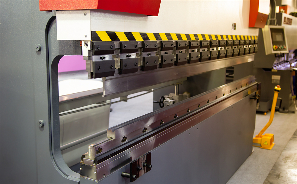
HARSLE press brakes are engineered to provide the repetitive accuracy needed to make these calculations meaningful. However, even the most advanced CNC system requires accurate input data. Without a solid grasp of BA and BD, even a high-end machine cannot compensate for incorrect flat pattern dimensions. This guide provides a deep dive into the mathematical foundations and practical applications of these calculations in a modern shop environment.
The Significance of the Neutral Axis
The neutral axis is the pivot point of all bending calculations. In a perfect world, the neutral axis would stay exactly in the center of the material thickness. However, in reality, as the metal is bent, the neutral axis shifts toward the inside of the bend. The position of this axis is defined by the K-factor, which is the ratio of the distance from the inside surface to the neutral axis divided by the total material thickness. Understanding this shift is the first step in learning how to calculate bend allowance and bend deduction on a press brake accurately.
Core Parameters for Bending Calculations
Before diving into the formulas, one must identify the four critical variables that influence every bend. These parameters are the foundation of any calculation performed on the shop floor or in a CAD/CAM environment.
- Material Thickness (T): This is the gauge of the sheet metal. Even small variations in thickness—common in lower-quality batches of steel—can significantly impact the final bend dimensions.
- Inside Bend Radius (R): This is the radius of the internal curve of the bend. In air bending, the radius is not determined by the punch tip alone but is typically about 15-20% of the V-die opening width.
- Bend Angle (B): This is the angle to which the part is bent, usually measured as the included angle or the complementary angle. For most formulas, the complementary angle (the angle the metal has moved from flat) is used.
- K-Factor (K): A constant that represents the location of the neutral axis. It typically ranges from 0.3 to 0.5 depending on the material type and the ratio of the bend radius to the thickness.
Each of these parameters interacts with the others. For instance, if you change your V-die to a wider opening, your inside bend radius will increase, which in turn changes your bend allowance and bend deduction. This is why consistency in tooling selection is just as important as the math itself. When using a HARSLE press brake, the CNC controller often allows you to input these variables directly, but knowing the manual calculation ensures you can troubleshoot errors when the physical part doesn’t match the digital model.
Calculation Method: Step-by-Step Formulas
To calculate bend allowance and bend deduction on a press brake, we follow a logical mathematical progression. Let’s break down the formulas used by engineers worldwide.
1. Calculating Bend Allowance (BA)
The formula for Bend Allowance determines the length of the neutral axis within the bend. The standard formula is:
BA = A * (π / 180) * (R + K * T)
Where:
A = Bend angle (in degrees)
R = Inside bend radius
K = K-factor
T = Material thickness
For a standard 90-degree bend, the formula simplifies slightly, but the principle remains: you are calculating the circumference of a partial circle defined by the neutral axis.
2. Calculating Outside Setback (OSSB)
Before we can find the Bend Deduction, we must find the Outside Setback. The OSSB is the distance from the apex of the bend (where the two straight flanges would meet in space) to the start of the bend radius.
OSSB = tan(A / 2) * (R + T)
For a 90-degree bend, tan(45) is 1, so the OSSB is simply R + T.
3. Calculating Bend Deduction (BD)
The Bend Deduction is the most practical value for many fabricators because it tells you exactly how much to subtract from the sum of your desired flange lengths to get your flat blank length. The formula is:
BD = (2 * OSSB) – BA
By calculating the BD, you can quickly determine the flat pattern: Flat Length = Flange 1 + Flange 2 – BD. This ensures that after the metal stretches and compresses during the stroke of the press brake, the final dimensions are spot on.
Parameter Table: K-Factor and Material Constants
The K-factor is often the most difficult variable to pin down because it changes based on the material’s ductility and the bending method. Below is a general reference table for K-factors used in common air bending applications.
| Material Type | R/T Ratio (Radius/Thickness) | Recommended K-Factor |
|---|---|---|
| Soft Copper / Aluminum | Under 1.0 | 0.33 – 0.35 |
| Cold Rolled Steel | 1.0 to 1.5 | 0.38 – 0.42 |
| Stainless Steel | 1.0 to 2.0 | 0.35 – 0.40 |
| Hard Materials (Spring Steel) | Over 2.0 | 0.45 – 0.50 |
| General Purpose (Default) | Standard | 0.447 |
Note: These values are starting points. For high-precision work, it is recommended to perform a test bend on a scrap piece of the same material and thickness to reverse-calculate the exact K-factor for your specific HARSLE machine and tooling setup.
Common Engineering Mistakes in Bending Calculations
Even with the right formulas, errors can creep into the fabrication process. One of the most common mistakes is ignoring the grain direction of the metal. Sheet metal is rolled at the mill, creating a grain. Bending with the grain (longitudinal) is easier but more prone to cracking and offers a different springback profile than bending across the grain (transverse). This affects the actual inside radius achieved, which in turn alters the BA and BD.
Another frequent error is incorrectly estimating the inside radius in air bending. Many beginners assume the inside radius equals the punch tip radius. In reality, in air bending, the metal forms a natural radius based on the V-die width. If you use a punch with a 1mm radius but a 16mm V-die, your actual inside radius might be closer to 2.5mm. Using 1mm in your calculations will result in a part that is significantly out of tolerance.
Finally, failing to account for springback can ruin a batch of parts. While springback affects the angle more than the flat length, the compensation required to hit the target angle can slightly shift the neutral axis. Advanced HARSLE CNC press brakes feature springback compensation systems, but the initial flat pattern must still be calculated based on the final intended geometry.
Selection Checklist: Choosing the Right Press Brake and Tooling
To achieve the precision required by these calculations, your equipment must be up to the task. Use this checklist when selecting a HARSLE press brake or setting up a new job:
- Tonnage Requirement: Ensure the machine has enough force to bend the material thickness at the desired radius without straining the frame.
- CNC Controller Capabilities: Does the controller support automatic BA/BD calculation? HARSLE machines often feature Delem or Cybelec controllers that simplify this process.
- Tooling Quality: Use precision-ground tooling. Worn dies change the V-opening width, which invalidates your radius assumptions.
- Backgauge Accuracy: A calculation is only as good as the positioning. Ensure the backgauge is calibrated to the center of the bend.
- Material Consistency: Verify the actual thickness of your material with calipers rather than relying on the nominal gauge.
- Repeatability: Choose a hydraulic system with high repeatability (like the HARSLE WE67K series) to ensure that once the calculation is perfected, every part is identical.
Frequently Asked Questions (FAQ)
What is the difference between Bend Allowance and Bend Deduction?
Bend Allowance is the length of the arc along the neutral axis of the bend. Bend Deduction is the amount of material you subtract from the outside dimensions of the part to find the flat blank length. BA is about the material inside the bend; BD is about the adjustment needed for the flat pattern.
How does the V-die width affect the Bend Deduction?
The V-die width determines the inside radius of the bend in air bending (the 20% rule). A wider die creates a larger radius. A larger radius increases the Bend Allowance and changes the Bend Deduction. If you change your die, you must recalculate your BD.
Can I use a K-factor of 0.5 for everything?
While 0.447 or 0.5 is a common default, it is rarely perfectly accurate. Using 0.5 assumes the neutral axis is exactly in the middle of the material, which only happens in very specific conditions. For precision work, use the table provided or perform a test bend.
Why is my part too long even though I used the formula?
This usually happens because the actual inside radius achieved on the press brake is larger than the radius used in the formula. Check your V-die width and ensure you are calculating the ‘actual’ radius, not just using the punch tip radius.
Does the bend angle affect the K-factor?
Technically, the K-factor is a property of the material and the ratio of radius to thickness, but extreme angles can cause additional material thinning, which might require a slight adjustment to the effective K-factor used in calculations.
How do HARSLE press brakes help with these calculations?
HARSLE CNC press brakes come equipped with advanced software that allows operators to input material type, thickness, and desired angle. The controller then uses built-in databases and formulas to calculate the required backgauge position and depth of stroke, effectively handling the BA and BD math automatically for the operator.


