CNC Press Brake Programming Basics for Efficient Sheet Metal Production

Technical Overview of CNC Press Brake Programming
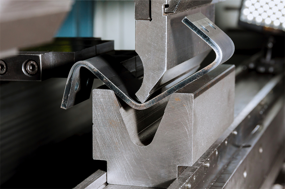
In the modern landscape of metal fabrication, the transition from manual operation to Computer Numerical Control (CNC) has revolutionized how we approach sheet metal bending. CNC press brake programming basics for efficient sheet metal production are centered around the ability to translate complex 3D designs into precise mechanical movements. At its core, CNC programming involves instructing the machine’s hydraulic or electric systems to move the ram (Y-axis) and the backgauge (X, R, Z axes) to specific coordinates, ensuring that every bend is consistent across thousands of parts.
The evolution of programming has moved from manual data entry of G-codes to sophisticated graphical user interfaces (GUIs). Modern HARSLE CNC press brakes often utilize controllers like Delem, Cybelec, or ESA, which allow operators to draw the part directly on the screen or import CAD files. This shift has significantly reduced the barrier to entry for operators while increasing the speed of setup. Efficient programming is not just about making a single bend; it is about optimizing the sequence of bends to minimize material handling and prevent collisions between the workpiece and the machine frame or tooling.

Furthermore, technical efficiency in programming relies heavily on the integration of offline programming software. By simulating the bending process on a computer before the first piece of metal is even touched, engineers can identify potential issues such as tool interference or unreachable bend sequences. This ‘first-time-right’ approach is the cornerstone of high-volume, high-precision manufacturing. Understanding the relationship between the machine’s physical limits and the software’s virtual environment is the first step toward mastering CNC press brake programming basics for efficient sheet metal production.
Core Parameters in CNC Programming
To achieve precision, an operator must understand the core parameters that define a CNC program. The most critical is the Y-axis, which controls the vertical movement of the ram. In a synchronized CNC system, Y1 and Y2 represent the left and right cylinders, respectively. Programming these involves setting the ‘target’ position to achieve a specific angle. Because materials have different degrees of elasticity, the Y-axis must be programmed to over-bend slightly to account for springback, a process often automated by modern CNC controllers using material databases.
The Backgauge System (X, R, Z axes) is equally vital. The X-axis determines the flange length by moving the backgauge fingers forward or backward. The R-axis controls the vertical height of the fingers, which is essential when bending parts with pre-existing flanges that might interfere with a flat gauge. The Z1 and Z2 axes control the lateral movement, allowing the fingers to spread apart or move closer together to support different widths of sheet metal. Efficient programming involves minimizing the travel time of these axes between steps to reduce the overall cycle time.
Another essential parameter is Crowning. As the press brake applies pressure, the bed and the ram naturally deflect or ‘bow’ in the center. Without compensation, this results in a ‘canoe effect’ where the angle in the middle of the part is wider than at the ends. CNC programming allows for the control of hydraulic or mechanical crowning systems that counteract this deflection in real-time. By inputting the material length and thickness, the controller calculates the necessary compensation to ensure a uniform angle across the entire length of the bend.
Finally, Speed and Dwell Time are parameters that impact both quality and safety. The ‘approach speed’ allows the ram to move quickly toward the metal, while the ‘bending speed’ is much slower to ensure accuracy and operator safety. ‘Dwell time’ at the bottom of the stroke allows the material to ‘set,’ which can be particularly useful for heavy-gauge materials or when trying to minimize springback. Mastering these parameters is fundamental to CNC press brake programming basics for efficient sheet metal production.
Calculation Methods for Precision Bending
Accurate programming is impossible without precise calculations. The most important calculation in sheet metal bending is the Bend Allowance (BA). When metal is bent, the outer radius stretches and the inner radius compresses. Between these two is the ‘neutral axis,’ which remains the same length. The formula for Bend Allowance is: BA = Δ(π/180) * (R + K * T), where Δ is the bend angle, R is the inside radius, T is the material thickness, and K is the K-factor (the ratio of the neutral axis position to the thickness).
The K-Factor is a critical variable that changes based on the material type and the bending method (air bending vs. bottoming). For most mild steel applications using air bending, a K-factor of 0.44 to 0.48 is standard. However, for precision work, fabricators often perform test bends to determine the exact K-factor for a specific batch of material. Programming this value correctly into the CNC controller ensures that the flat pattern length is calculated accurately, preventing the final part from being too long or too short.
Tonnage Calculation is another necessity to prevent machine damage and ensure tool longevity. The required force depends on the material’s tensile strength, thickness, and the V-opening of the die. A common rule of thumb for mild steel is: P = (650 * T² * L) / V, where P is tonnage, T is thickness, L is length, and V is the die opening. If the programmed tonnage exceeds the limits of the tooling or the machine, it can lead to catastrophic failure. Modern CNC systems often calculate this automatically, but the operator must verify the inputs to ensure safety.
Standard Parameter Table for Mild Steel Bending
The following table provides a baseline for programming HARSLE CNC press brakes when working with standard mild steel (Tensile strength approx. 450 MPa). These values are intended for air bending applications.
| Material Thickness (mm) | Recommended V-Opening (mm) | Min. Flange Length (mm) | Inside Radius (mm) | Required Tonnage per Meter |
|---|---|---|---|---|
| 1.0 | 8 | 5.5 | 1.3 | 7 |
| 1.5 | 12 | 8.5 | 2.0 | 11 |
| 2.0 | 16 | 11.5 | 2.6 | 17 |
| 3.0 | 24 | 17.0 | 4.0 | 25 |
| 4.0 | 32 | 22.0 | 5.3 | 33 |
| 6.0 | 50 | 35.0 | 8.0 | 50 |
| 8.0 | 63 | 45.0 | 10.5 | 75 |
Note: The V-opening is typically chosen as 6 to 8 times the material thickness for materials up to 6mm, and 10 to 12 times for thicker plates. Choosing a smaller V-opening increases the required tonnage and the risk of marking the material, while a larger V-opening increases the minimum flange length and the inside radius.
Common Engineering Mistakes in CNC Programming
One of the most frequent mistakes in CNC press brake programming is incorrect tool selection in the software. If the programmed punch and die dimensions do not match the physical tools installed on the machine, the CNC controller will calculate the wrong depth (Y-axis), leading to incorrect angles. Furthermore, failing to account for the ‘punch tip radius’ can lead to unexpected material cracking, especially in high-strength steels or aluminum. Always ensure the tool library in your CNC controller is updated and accurate.
Another common error is ignoring the bend sequence. In complex parts with multiple bends, the order in which you execute the bends is paramount. An inefficient sequence can result in the part hitting the ram or the backgauge during the third or fourth bend. While many modern CNC controllers have ‘auto-sequence’ features, they are not infallible. Operators should manually review the simulation to ensure there is enough clearance for the part to be rotated and flipped without interference.
Neglecting material grain direction is a subtle but impactful mistake. Sheet metal has a ‘grain’ resulting from the rolling process at the mill. Bending with the grain (parallel) is easier but more prone to cracking, while bending against the grain (perpendicular) requires more force but offers a tighter radius and better structural integrity. If a program is optimized for one direction but the operator loads the sheet in another, the springback and required tonnage will change, leading to inconsistent parts.
Finally, many engineers fail to program safety zones. CNC backgauges move with significant speed and force. If the program does not include ‘retract’ movements, the backgauge fingers might stay in a position where the material hits them as it bends upward (the ‘whip-up’ effect). This not only ruins the part but can also damage the precision lead screws of the backgauge system. Efficient programming always includes a programmed retract for the X-axis during the bending phase.
Selection Checklist for Efficient CNC Programming
When selecting a CNC press brake or upgrading your current workflow to improve programming efficiency, consider the following checklist:
- Controller Capability: Does the controller support 2D or 3D graphical programming? Can it import DXF, STEP, or IGES files directly?
- Offline Software Integration: Is there compatible offline software (like Delem Profile-T or specialized CAM software) to allow programming while the machine is running another job?
- Automatic Crowning: Does the machine have a CNC-controlled crowning system to ensure angle consistency without manual shimming?
- Axis Configuration: Do you have enough axes (X, R, Z1, Z2) to handle the complexity of your parts without manual backgauge adjustments?
- Tooling Library: Does the software allow for a comprehensive library of punches and dies, including custom-shaped tools?
- Angle Measurement Systems: Consider machines with integrated laser angle measurement for real-time corrections, which eliminates the need for manual ‘trial and error’ programming.
- Simulation Features: Does the controller provide collision detection and bend sequence optimization?
Frequently Asked Questions (FAQ)
1. What is the difference between 2D and 3D CNC programming?
2D programming allows you to draw the profile of the part and define the bend sequence in a flat plane. It is faster for simple parts. 3D programming allows you to import a full 3D model, providing a realistic simulation of the bending process, which is essential for complex parts with multiple flanges in different directions to prevent collisions.
2. How do I handle springback in CNC programming?
Springback is handled by ‘over-bending.’ Most CNC controllers have a built-in database where you can input the material type. The controller then automatically adds a few degrees to the bend. For ultimate precision, laser angle sensors can measure the angle during the bend and adjust the Y-axis in real-time to hit the exact target.
3. Can I use the same program for different materials?
No. Even if the thickness is the same, different materials (e.g., Stainless Steel vs. Aluminum) have different tensile strengths and springback characteristics. You must adjust the material settings in the CNC program to ensure the controller calculates the correct tonnage and depth.
4. Why is my backgauge moving to the wrong position?
This is often due to an incorrect ‘origin’ or ‘calibration’ setting. Ensure that the machine has been properly homed at startup. Also, check if the ‘finger offset’ is correctly programmed in the tool settings, as the physical shape of the backgauge finger affects where the material actually stops.
5. How does offline programming save money?
Offline programming allows the engineer to create and simulate programs on a PC. This means the press brake stays in production rather than sitting idle while an operator types in data. It also reduces scrap by identifying errors in the virtual environment before any metal is cut or bent.


