Comprehensive Guide to Troubleshooting Press Brake Hydraulic Problems in Metal Fabrication Equipment

Technical Overview of Press Brake Hydraulic Systems
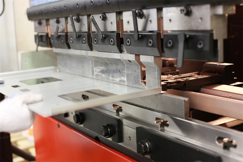
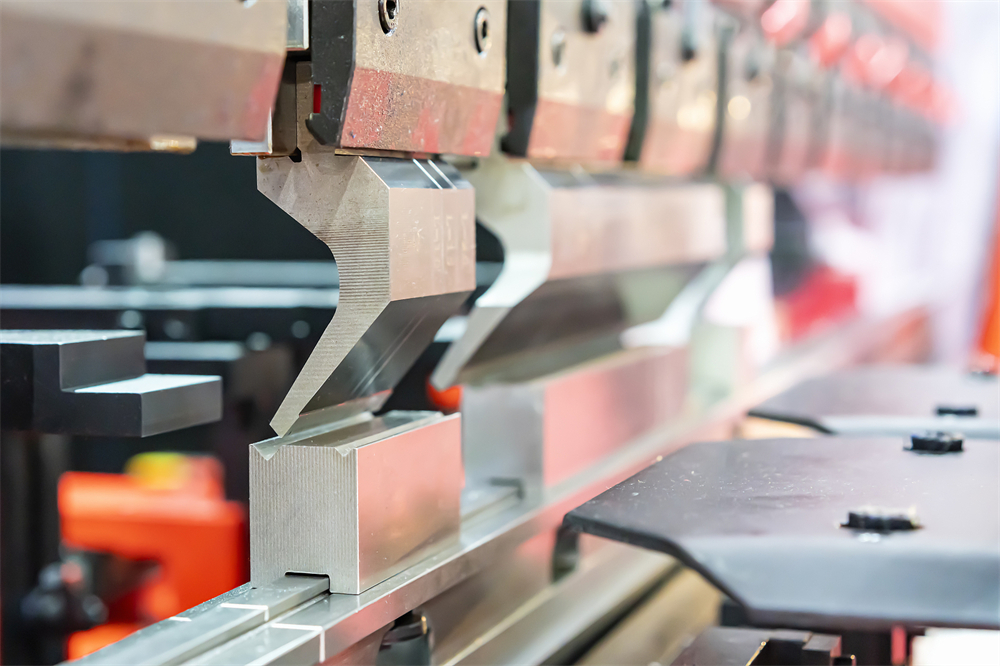
In the realm of metal fabrication, the hydraulic press brake stands as a cornerstone of precision and power. The hydraulic system is the lifeblood of these machines, converting electrical energy into mechanical force through the medium of pressurized fluid. Understanding the intricacies of this system is the first step in effective Troubleshooting Press Brake Hydraulic Problems In Metal Fabrication Equipment. A typical hydraulic circuit in a modern CNC press brake consists of a motor-driven pump, a reservoir, various control valves (including proportional and directional valves), and the hydraulic cylinders that drive the ram.
The efficiency of a press brake is largely dependent on the synchronization of its hydraulic cylinders. In high-end CNC models, this is achieved through a sophisticated feedback loop involving linear encoders and electro-hydraulic proportional valves. These valves regulate the flow of oil to each cylinder with millisecond precision, ensuring that the ram remains perfectly level even under off-center loading. When this synchronization fails, the resulting angular inaccuracies can lead to significant material waste and production downtime.
Hydraulic systems are generally categorized into open-loop and closed-loop systems. Open-loop systems are simpler and often found in older or entry-level machines, where the pump draws oil from the tank and sends it through the valves to the cylinders before returning it to the tank. Closed-loop systems, often utilizing servo-pump technology, offer higher energy efficiency and faster response times by directly controlling the motor speed to regulate flow and pressure. Troubleshooting these systems requires a deep understanding of both hydraulic principles and electronic control interfaces.
Furthermore, the physical properties of the hydraulic oil itself—such as viscosity, cleanliness, and temperature—play a critical role in system performance. Contamination is the leading cause of hydraulic failure, accounting for nearly 80% of all issues. Microscopic particles can score valve seats, clog orifices, and accelerate wear on pump components. Therefore, any technical overview of press brake hydraulics must emphasize the importance of filtration and regular fluid analysis to maintain the integrity of the metal fabrication equipment.
Core Parameters of Hydraulic Press Brakes
When Troubleshooting Press Brake Hydraulic Problems In Metal Fabrication Equipment, technicians must monitor several core parameters that define the machine’s operational health. The most critical parameter is the system pressure, usually measured in bars or PSI. This pressure determines the tonnage the machine can exert. If the pressure fails to reach the programmed setpoint, the machine will be unable to bend thicker materials or achieve the required bend angle.
Flow rate, measured in liters per minute (LPM), is another vital parameter. It dictates the speed of the ram during the approach, pressing, and return phases. A drop in flow rate often indicates a worn pump or an internal leak within the control valves. In CNC machines, the flow rate is dynamically adjusted to match the bending cycle requirements, and discrepancies here can lead to jerky movements or inconsistent cycle times.
Oil temperature is a parameter that is frequently overlooked until it causes a system shutdown. The ideal operating temperature for hydraulic oil in a press brake is typically between 35°C and 55°C (95°F to 131°F). If the temperature exceeds 60°C, the oil’s viscosity drops significantly, leading to increased internal leakage, reduced lubrication, and potential damage to seals and O-rings. High temperatures are often a symptom of inefficient cooling or excessive friction within the system.
Finally, the cleanliness level of the oil, often rated by the ISO 4406 standard, is a core parameter for longevity. For modern electro-hydraulic press brakes, a cleanliness level of ISO 16/14/11 or better is usually required. Monitoring these parameters through integrated sensors or manual gauges allows operators to identify trends and perform predictive maintenance before a catastrophic failure occurs.
Calculation Method for Bending Force and Hydraulic Requirements
To effectively troubleshoot and operate a press brake, one must understand the relationship between the material properties and the hydraulic force required. The standard formula for calculating the bending force (P) in V-bending is:
P = (650 * S² * L) / V
Where:
P = Bending force in Kilonewtons (kN)
S = Material thickness in millimeters (mm)
L = Length of the bend in meters (m)
V = V-die opening width in millimeters (mm)
Once the required force is determined, the hydraulic system must be able to generate sufficient pressure. The pressure (p) required in the cylinders is calculated by dividing the force (P) by the total effective area (A) of the hydraulic pistons: p = P / A. If the calculated pressure exceeds the machine’s maximum rated pressure, the operator must either increase the V-die opening or reduce the bend length to avoid overloading the hydraulic circuit.
Another important calculation involves the cycle time, which is dependent on the pump’s flow rate. The speed of the ram (v) is calculated as v = Q / A, where Q is the flow rate and A is the cylinder area. During Troubleshooting Press Brake Hydraulic Problems In Metal Fabrication Equipment, comparing the theoretical speed with the actual measured speed can help pinpoint issues like pump cavitation or bypass leakage in the valves. Understanding these calculations ensures that the machine is operated within its design limits, preventing premature hydraulic wear.
Hydraulic System Parameter Table
The following table provides typical hydraulic specifications for various tonnages of industrial press brakes. These values serve as a reference point for troubleshooting and system evaluation.
| Machine Tonnage (Tons) | Max System Pressure (Bar) | Pump Flow Rate (L/min) | Oil Tank Capacity (L) | Typical Motor Power (kW) |
|---|---|---|---|---|
| 40T | 200 – 220 | 15 – 25 | 100 – 150 | 4.0 – 5.5 |
| 100T | 240 – 260 | 40 – 60 | 250 – 350 | 7.5 – 11.0 |
| 200T | 280 – 300 | 80 – 120 | 500 – 700 | 15.0 – 22.0 |
| 400T | 300 – 320 | 150 – 250 | 1000 – 1500 | 30.0 – 45.0 |
Common Engineering Mistakes in Hydraulic Maintenance
One of the most frequent engineering mistakes in the maintenance of metal fabrication equipment is the use of incorrect hydraulic oil. Many operators assume that any hydraulic fluid will suffice, but press brakes require specific anti-wear (AW) oils with stable viscosity indexes. Using oil that is too thick can cause pump cavitation and sluggish response in cold starts, while oil that is too thin fails to provide adequate lubrication at operating temperatures, leading to accelerated component wear.
Another common error is neglecting the air filter or breather cap on the hydraulic reservoir. As the oil level fluctuates during the machine cycle, air is drawn into and expelled from the tank. If the breather is clogged, a vacuum can form, causing the pump to cavitate. Conversely, if the breather is missing or damaged, moisture and airborne contaminants can enter the oil, leading to oxidation and the formation of sludge that clogs sensitive proportional valves.
Improper adjustment of relief valves is also a significant issue. Technicians sometimes increase the relief valve setting to “fix” a lack of bending power. However, if the underlying problem is a worn pump or internal leak, raising the pressure limit only puts excessive stress on the hoses, seals, and structural components of the machine, potentially leading to a dangerous high-pressure burst. Pressure settings should always be calibrated according to the manufacturer’s specifications using certified gauges.
Finally, many maintenance routines fail to address the hydraulic accumulator. Accumulators are used to store energy and dampen pressure spikes. Over time, the nitrogen pre-charge in the accumulator can leak. If the pre-charge is too low, the machine may exhibit jerky movements or loud “hammering” noises during the transition from high-speed approach to slow-speed pressing. Regularly checking and recharging the accumulator is essential for smooth hydraulic operation.
Selection Checklist for Press Brake Hydraulic Systems
When purchasing or upgrading metal fabrication equipment, the hydraulic system’s quality should be a primary consideration. Use the following checklist to evaluate the hydraulic components of a press brake:
- Pump Type: Does the machine use a high-quality piston pump or a gear pump? Piston pumps are generally more durable and efficient for high-pressure applications.
- Valve Brand: Are the proportional and directional valves from reputable manufacturers like Rexroth, Hoerbiger, or Vickers? Reliable valves are critical for CNC precision.
- Filtration System: Does the system include a high-efficiency return-line filter and a suction strainer? Is there a visual or electronic clogging indicator?
- Cooling Capacity: Is there an integrated oil cooler (air or water-cooled)? This is essential for machines operating in multi-shift environments or hot climates.
- Sealing Technology: Are the cylinder seals made of high-grade materials like polyurethane or Viton? Quality seals prevent external leaks and internal bypass.
- Monitoring Sensors: Does the machine have sensors for oil level, temperature, and pressure that interface with the CNC controller for safety shutdowns?
- Ease of Access: Are the hydraulic components easily accessible for maintenance and troubleshooting? Compact designs that hide valves can significantly increase repair time.
Frequently Asked Questions (FAQ)
1. Why is my press brake making a loud whining noise?
A loud whining or growling noise is usually a sign of pump cavitation. This occurs when the pump is starved of oil, often due to a clogged suction filter, a blocked reservoir breather, or oil that is too viscous for the ambient temperature. It can also be caused by air entering the suction line through a loose fitting or a damaged shaft seal.
2. What causes the ram to drift down when the machine is stopped?
Ram drift is typically caused by internal leakage. This could be due to worn piston seals in the hydraulic cylinders or a leaking check valve/directional valve. In some cases, the counterbalance valve (which holds the weight of the ram) may be improperly adjusted or contaminated with debris, preventing it from sealing completely.
3. How often should I change the hydraulic oil in my press brake?
For most industrial applications, hydraulic oil should be changed every 2,000 to 4,000 operating hours, or at least once a year. However, the best practice is to perform oil analysis every six months. If the analysis shows high levels of oxidation, water content, or particulate contamination, the oil should be changed regardless of the hour count.
4. Why is the bending angle inconsistent across the length of the part?
While this can be a mechanical issue (like “crowning” problems), it is often hydraulic. If the synchronization between the two cylinders is off, one side of the ram may be slightly lower than the other. This is usually a problem with the proportional valves or the feedback from the linear encoders. Troubleshooting Press Brake Hydraulic Problems In Metal Fabrication Equipment in this case involves checking the valve calibration and ensuring the encoders are clean and secure.
5. Can I use standard motor oil in my press brake’s hydraulic system?
No. Motor oil contains detergents and additives that are not compatible with hydraulic systems. It can cause foaming, seal swelling, and will not provide the necessary anti-wear properties required for high-pressure hydraulic pumps. Always use a dedicated ISO VG 32 or VG 46 anti-wear hydraulic oil as specified by the manufacturer.
6. What should I do if the oil temperature exceeds 60°C?
If the oil is overheating, first check the oil level; low oil levels reduce the reservoir’s ability to dissipate heat. Next, inspect the oil cooler for dust or debris blockage. If the cooling system is functional, the heat may be caused by a relief valve that is stuck open or a pump that is severely worn and generating excessive internal friction.


