How Does a Press Brake Work? A Complete Guide to Metal Bending

How does a press brake work? To understand this fundamental process, one must look beyond the simple act of folding metal and examine the sophisticated interplay of hydraulic force, precision mechanics, and material science. At its core, a press brake is a machine tool designed to bend sheet and plate material, most commonly sheet metal, by clamping it between a matching punch and die. While the concept seems straightforward, the engineering required to achieve repeatable, micron-level accuracy across a three-meter workpiece involves complex synchronization of force and positioning.
Understanding How a Press Brake Works: Mechanical and Physical Principles

A press brake operates on the principle of force application to deform metal past its yield point but within its ultimate tensile strength. The machine consists of two main structural components: the upper movable beam (the ram) and the lower fixed table (the bed). To understand how a press brake works in a modern context, we must differentiate between the various driving mechanisms—primarily hydraulic, electric, and hybrid systems. In a hydraulic system, high-pressure oil is pumped into cylinders that drive the ram downward. In an electric system, high-torque servo motors drive ball screws or belts to achieve the same motion with significantly higher speed and precision.
The Tooling Interface: Punch and Die
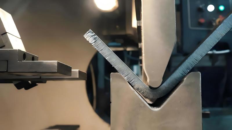
The actual bending occurs at the interface of the punch (upper tool) and the die (lower tool). The punch is a knife-like tool that forces the metal into the V-shaped opening of the die. The depth to which the punch penetrates the die determines the final bending angle. This process is governed by the geometry of the tools and the mechanical properties of the workpiece. Modern CNC (Computer Numerical Control) systems allow for precise control of this penetration depth, enabling angles to be achieved within fractions of a degree.
In the world of precision fabrication, the press brake is the bridge between a flat 2D design and a structural 3D reality. Its accuracy defines the success of every subsequent assembly process.
Why Understanding How a Press Brake Works is Essential for Engineering Precision
In sheet metal fabrication, precision is everything. If an engineer or operator does not fully grasp how a press brake works, they risk producing parts with inconsistent angles, cracked bends, or excessive internal stresses. Proper knowledge of the machine’s mechanics allows for the optimization of the production cycle. For instance, understanding the ‘neutral axis’ of a bend is critical for calculating the correct blank length. When metal is bent, the exterior of the bend is stretched (tension) while the interior is compressed. Somewhere in between lies the neutral axis, which maintains its original length.
Furthermore, knowing the limitations of the machine’s tonnage and the structural deflection of the frame (often called ‘yawning’) is vital for maintaining accuracy. High-end machines utilize ‘crowning’ systems—mechanical or hydraulic compensations in the bed that counteract the natural bowing of the machine under heavy loads. Without this understanding, long parts would invariably have a ‘canoeing’ effect, where the angle in the middle of the part is different from the angles at the ends.
Key Factors to Consider in Press Brake Operation
When evaluating how a press brake works for a specific application, several technical variables must be analyzed:
- Material Type: Stainless steel, aluminum, and carbon steel all have different yield strengths and springback characteristics.
- Bending Radius: The internal radius of the bend must be appropriate for the material thickness to prevent fracturing.
- Tonnage Capacity: The amount of force required to perform a bend, measured in tons or kilonewtons.
- Backgauge Accuracy: The system that positions the sheet metal relative to the tools, ensuring the bend occurs at the exact location specified in the drawing.
- Stroke and Throat Depth: Physical dimensions that limit the size and complexity of the parts that can be fabricated.
Technical Explanation and Tonnage Calculation
To calculate the force required for a bend, engineers use a specific formula. The tonnage is influenced by the material thickness, the length of the bend, the tensile strength of the metal, and the width of the die opening (V-opening). The standard empirical formula for air bending mild steel is as follows:
P = (K * L * S^2 * Sigma) / V
Where:
- P: Bending force in tons.
- K: A constant (usually 1.42 for air bending).
- L: Length of the sheet in meters.
- S: Material thickness in millimeters.
- Sigma: Tensile strength of the material (typically around 45 kg/mm2 for mild steel).
- V: Width of the die opening in millimeters.
A crucial rule of thumb in the industry is that the V-opening (V) should be approximately 8 times the material thickness (S) for materials up to 3mm thick. For thicker plates, this ratio may increase to 10 or 12 times the thickness to manage the increased tonnage requirements and prevent tool damage.
V-Opening and Tonnage Relationship Table
| Material Thickness (mm) | Recommended V-Opening (mm) | Min Flange Length (mm) | Approx. Tonnage per Meter (Mild Steel) |
|---|---|---|---|
| 1.0 | 8 | 5.5 | 7 |
| 1.5 | 12 | 8.5 | 11 |
| 2.0 | 16 | 11.5 | 14 |
| 3.0 | 24 | 17.0 | 22 |
| 4.0 | 32 | 23.0 | 32 |
| 6.0 | 50 | 35.0 | 48 |
Comparison of Press Brake Technologies
As technology has evolved, so has the way these machines generate force. Choosing the right machine requires a comparison of their driving systems.
| Feature | Hydraulic Press Brake | Electric Press Brake | Hybrid Press Brake |
|---|---|---|---|
| Force Source | Hydraulic Cylinders | Servo Motors & Ball Screws | Servo-Pump & Small Oil Reservoir |
| Energy Efficiency | Moderate (Pump runs constantly) | High (Energy only used during stroke) | High (Very efficient) |
| Precision | Good (+/- 0.01mm) | Excellent (+/- 0.001mm) | Excellent (+/- 0.005mm) |
| Speed | Standard | Very High | High |
| Maintenance | High (Oil changes, leaks) | Low (Mechanical focus) | Moderate |
| Tonnage Range | Up to 3000+ Tons | Usually up to 150 Tons | Up to 1000 Tons |
Step-by-Step Guide on How a Press Brake Works in a Modern Factory
- Setup and Tooling Selection: The operator selects the appropriate punch and die based on the material thickness and desired internal radius. The tools are clamped into the ram and bed.
- CNC Programming: The bending sequence is programmed into the CNC controller. This includes the bend angle, backgauge position, and material thickness. Modern controllers can simulate the bend to check for tool interference.
- Material Positioning: The operator places the sheet metal against the backgauge fingers. The backgauge ensures the bend line is perfectly aligned with the punch.
- The Bending Cycle: The operator activates the foot pedal. The ram descends at a rapid approach speed, transitions to a slower pressing speed just before contact, and then forces the metal into the die.
- Decompression and Return: Once the target depth is reached, the machine pauses briefly (dwell time) to ensure the angle is set, then slowly releases pressure (decompression) to avoid ‘kickback’ before returning to the top of its stroke.
- Measurement and Correction: The first part is measured using a protractor. If springback has caused the angle to be too wide, the operator enters a correction into the CNC, and the machine adjusts the depth for the next part.
Common Mistakes in Press Brake Operation
One of the most frequent mistakes is ignoring the ‘grain direction’ of the sheet metal. Metal is rolled at the mill, creating a grain. Bending parallel to the grain increases the risk of cracking, whereas bending perpendicular to the grain provides the strongest result. Another common error is ‘over-tonning.’ If an operator attempts to bend a small, thick piece using a narrow die opening, the concentrated force can exceed the tool’s load limit, resulting in a ‘shattered’ die or a damaged ram.
Precision is not a matter of luck; it is a matter of mathematics and the disciplined application of mechanical force.
Finally, neglecting the ‘air bend’ vs. ‘bottoming’ distinction leads to confusion. Most modern CNC machines use air bending, where the part only touches the two edges of the die and the tip of the punch. This requires less force and is more flexible, but it is highly sensitive to material thickness variations. Bottoming requires much higher tonnage as the punch forces the metal to conform exactly to the die’s shape, which can eliminate springback but risks machine wear.
Industry Applications for Precision Metal Bending
The versatility of the press brake makes it indispensable across various sectors:
- Aerospace: Fabrication of lightweight brackets and structural ribs using specialized aluminum alloys.
- Automotive: Production of chassis components, battery housings for EVs, and intricate interior supports.
- Construction: Large-scale bending of structural steel plates for bridges and heavy-duty building frames.
- Electronics: High-precision bending of small copper or aluminum enclosures for servers and telecommunications gear.
- Kitchen Equipment: Forming stainless steel surfaces for commercial refrigeration and food preparation.
Conclusion
Understanding how a press brake works is the cornerstone of successful sheet metal fabrication. From the basic mechanics of the ram and bed to the complex physics of tonnage calculations and springback compensation, every detail impacts the final product. For factory owners and engineers, the choice between hydraulic, electric, and hybrid systems depends on the specific balance of force, precision, and efficiency required for their production goals. By following best practices in tool selection, CNC programming, and safety, manufacturers can ensure that their bending operations remain both productive and highly accurate.
FAQ
What is springback in metal bending?
Springback is the phenomenon where a metal part partially returns to its original shape after the bending force is removed. This happens because the elastic recovery of the material occurs once the pressure is released. CNC machines compensate for this by over-bending the part by a few degrees.
How do I choose the right V-opening for my die?
The industry standard for mild steel is to choose a V-opening that is 8 times the material thickness (8S). For thicker materials (over 6mm), a V-opening of 10 or 12 times the thickness is often used to reduce the required tonnage and prevent material cracking.
What is the difference between air bending and bottoming?
Air bending involves the punch pressing the material into the die without reaching the bottom, where the angle is determined by the depth of the stroke. Bottoming involves pressing the material completely into the die so it takes the tool’s exact shape. Air bending requires less force and is more versatile.
What is CNC crowning?
Crowning is a system built into the press brake bed or ram to compensate for the natural deflection (bowing) of the machine under load. It ensures that the bending force is distributed evenly across the entire length of the machine, resulting in a consistent angle from end to end.
Why is the K-factor important in press brake work?
The K-factor is a ratio that represents the location of the neutral axis relative to the material thickness. It is used to calculate the ‘bend allowance’ and ‘bend deduction,’ which are essential for determining the flat length of a part before it is bent.


