Technical Guide: Hydraulic Systems in Modern Press Brakes

Hydraulic systems in modern press brakes are vital for their precision and power, transforming sheet metal fabrication. Unlike early mechanical systems with flywheels and clutches, today’s machines rely on sophisticated fluid power. This shift has made understanding hydraulic systems crucial for engineers and factory managers who aim to enhance production efficiency and accuracy. These systems have evolved into servo-hybrid configurations, offering both high tonnage and micro-control for complex bending. With advancing material science and tighter tolerances, key components such as hydraulic manifolds, proportional valves, and feedback loops now play a critical role in ensuring the quality of the final product.
Understanding the Basics of Hydraulic Systems in Modern Press Brakes
A press brake’s hydraulic system operates based on Pascal’s Law, where pressure applied to a confined fluid is transmitted equally in all directions. An electric motor drives a hydraulic pump, generating fluid flow through a manifold into two cylinders, which move the ram (upper beam) to press the workpiece into the lower die. Modern systems use a closed-loop control, with the CNC unit constantly monitoring the ram’s position via linear scales. The data is processed rapidly to adjust oil flow through proportional valves, ensuring both cylinders (Y1 and Y2 axes) stay synchronized, even under off-center loads.
Modern press brake hydraulics are no longer just about raw force; they are about the micro-millimeter control of fluid dynamics to ensure perfect parallelism across the entire bed length.
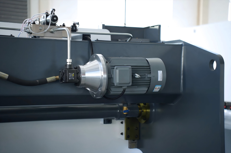
The system comprises several critical components: the reservoir, which stores the hydraulic oil; the pump (typically an axial piston pump or a gear pump); the valve manifold, which contains the logic and direction control valves; and the actuators or cylinders. The transition from simple on-off valves to proportional and servo-valves has been the most significant advancement, allowing for variable speeds and precise positioning during the bending cycle. This allows the machine to transition seamlessly from a rapid approach speed to a slow, controlled bending speed, and finally to a decompression and return phase.
Why Hydraulic Systems in Modern Press Brakes Matter in Sheet Metal Fabrication
Hydraulic systems in modern press brakes are crucial for providing consistent, repeatable force under varying conditions. Unlike mechanical brakes with fixed stroke and maximum tonnage only at the bottom, hydraulic brakes deliver full tonnage at any point in the ram’s travel. This flexibility is vital for air bending, where the depth of the punch into the die determines the bending angle. Additionally, hydraulic systems enable integrated crowning systems—either hydraulic or mechanical—that counteract the machine’s frame deflection under load. Without precise hydraulic control, maintaining a consistent angle over long bends, like a 4-meter sheet, would be impossible due to the ‘bowing’ effect of the press brake bed.
Reliability and safety are also major factors. Modern hydraulic circuits include redundant safety valves and pressure monitoring that can stop the ram instantly if an obstruction is detected or if a system failure occurs. For the factory owner, a well-engineered hydraulic system translates to lower scrap rates, faster setup times, and the ability to handle a wider variety of materials, from soft aluminum to high-tensile armored steel. The efficiency of the hydraulic system directly impacts the cycle time per part, making it a key performance indicator in high-volume production environments.
Key Factors to Consider for Hydraulic Systems in Modern Press Brakes
When evaluating a press brake, several technical factors regarding its hydraulic architecture must be analyzed. First is the valve technology. Proportional valves are now the industry standard, but the brand and response time of these valves (measured in milliseconds) determine how quickly the machine can correct for ram tilt. Second is the pump type. While standard induction motors with fixed-displacement pumps were common, modern machines increasingly use variable-displacement pumps or servo-driven pumps to reduce energy consumption and oil heating. Oil cooling and filtration are also paramount. Contaminated oil is the leading cause of hydraulic failure, as microscopic particles can score the precision-ground surfaces of proportional valves, leading to ‘sticking’ or erratic movement.
- Valve Manifold Integration: A compact manifold reduces the number of hoses and fittings, minimizing the risk of leaks and reducing fluid turbulence.
- Feedback Resolution: The resolution of the linear scales (often 0.001mm) must be matched by the hydraulic system’s ability to respond to those minute inputs.
- Thermal Management: Systems that include oil heaters (for cold starts) and efficient heat exchangers ensure the oil stays within its optimal viscosity range, usually 40 to 50 degrees Celsius.
- Cylinder Design: High-quality cylinders with specialized seals reduce friction and prevent ‘creep’ when the ram is holding a position under pressure.
Technical Explanation and Tonnage Calculation
Engineering a bend requires calculating the necessary force, known as tonnage. This calculation ensures that the hydraulic system is not overloaded and that the selected tooling is appropriate for the job. The required tonnage is influenced by the material’s tensile strength, thickness, and the width of the lower die opening (V-opening). The standard formula for estimating tonnage (P) in air bending is derived from the beam deflection principle.
P = (k * L * s^2 * UTS) / (V * 1000)
In this formula: P represents tonnage (metric tons); L is the sheet length (mm); s is the material thickness (mm); UTS is the Ultimate Tensile Strength of the material (N/mm²); V is the die opening width (mm); and k is a constant (typically 1.42 for air bending). For example, bending a 3mm thick stainless steel plate with a UTS of 600 N/mm² over a 2000mm length using a 24mm die would require significant hydraulic pressure. Engineers must also consider the ‘pressure per meter’ to ensure the machine’s frame can handle the localized load. The hydraulic system regulates pressure in the Y1 and Y2 cylinders, ensuring the force stays within the machine’s rated capacity while maintaining parallelism.
Comparison of Machine Hydraulic Technologies
As technology has advanced, two primary types of hydraulic systems have emerged in the top-tier press brake market: Conventional Proportional Systems and Servo-Hybrid Systems. The following table compares these two technologies across key engineering metrics.
| Metric | Conventional Proportional Hydraulic | Servo-Hybrid (Hybrid) System |
|---|---|---|
| Drive Method | Constant Speed AC Motor + Pump | Servo Motor + Bi-directional Pump |
| Energy Efficiency | Moderate (Pump runs constantly) | High (Pump runs only on demand) |
| Oil Volume | Large (e.g., 200-400 Liters) | Small (e.g., 50-100 Liters) |
| Heat Generation | High (Fluid bypass generates heat) | Very Low (Minimal fluid friction) |
| Cycle Speed | Standard Rapid/Bending speeds | Up to 30% faster cycle times |
| Maintenance | Regular oil and filter changes | Extended oil life due to less heat |
| Precision | +/- 0.01mm | +/- 0.005mm |
While conventional systems are robust and cost-effective for many applications, the servo-hybrid system is rapidly becoming the preference for high-precision and high-production environments. The hybrid system’s ability to nearly eliminate heat generation not only saves electricity but also maintains the oil’s viscosity, which is the primary factor in long-term bending consistency.
Step-by-Step Guide to the Hydraulic Bending Cycle
To understand the sophistication of modern hydraulics, one must look at the sequence of a single bend cycle. This process is orchestrated by the CNC controller in coordination with the hydraulic valves.
- Rapid Descent: The CNC opens the main flow valves, allowing gravity and pump pressure to bring the ram down quickly. To prevent cavitation, ‘filling valves’ allow oil to flow from the reservoir into the expanding cylinder volume.
- Mute Point: Just above the material, the ram slows down to the ‘bending speed.’ This is a safety and precision requirement, controlled by throttling the proportional valves.
- Bending Phase: As the punch touches the material, pressure builds. The CNC monitors the Y1/Y2 scales and adjusts the valves to ensure the ram remains perfectly level, even if the sheet is placed off-center.
- Dwell Time: At the bottom of the stroke, the system may hold pressure for a fraction of a second (dwell) to allow the material to ‘set’ and reduce springback.
- Decompression: This is a critical technical step. High-pressure oil is highly compressed. The system must release this pressure in a controlled manner before moving the ram upward to avoid ‘hydraulic shock’ which can damage pipes and seals.
- Return Stroke: The valves reverse the flow, and the ram returns to its top dead center (TDC) position at high speed.
Common Mistakes to Avoid
Even advanced hydraulic systems in modern press brakes can fail if mismanaged. A common mistake is neglecting oil quality, as hydraulic oil serves both as a power transmission fluid and a lubricant. Incorrect viscosity or unclean filters can cause ‘chatter’ in the ram movement. Another issue is operating the machine at maximum tonnage for extended periods, leading to thermal expansion, frame deviation, and premature seal wear. Additionally, failing to check cylinder synchronization can result in misalignment of the Y1 and Y2 axes, often indicating a failing proportional valve or a leak in the cylinder bypass, which should be addressed immediately to avoid permanent ram tilt.
Industry Applications
The versatility of these systems allows them to be used across diverse industries. In the automotive sector, hydraulic press brakes are used to form high-strength chassis components where precision is non-negotiable. In the heavy machinery industry, large-tonnage (1000 tons or more) tandem hydraulic brakes work in synchronization to bend long sections of crane booms or ship hull plates. Conversely, in the electronics industry, small, high-speed hybrid brakes produce intricate aluminum enclosures with tolerances measured in microns. The ability of the hydraulic system to adapt to these varying scales—from the delicate to the massive—is what makes it the backbone of modern sheet metal fabrication.
Conclusion
The evolution of hydraulic systems in modern press brakes represents a perfect marriage of mechanical power and electronic precision. From the fundamental principles of Pascal’s Law to the advanced efficiency of servo-hybrid drives, these systems continue to push the boundaries of what is possible in sheet metal forming. For engineers and buyers, the focus should remain on the quality of the valve logic, the efficiency of the thermal management, and the sophistication of the closed-loop feedback. As we move toward Industry 4.0, expect these hydraulic systems to become even more integrated, providing real-time data on machine health and material behavior, further solidifying their place as the heart of the fabrication shop.
FAQ
What is the main advantage of a servo-hybrid hydraulic system?
The primary advantage is energy efficiency and reduced heat. Since the motor only runs when the ram is moving, it consumes up to 60 percent less power and keeps the hydraulic oil cool, leading to higher precision and longer seal life.
How does air in the hydraulic lines affect bending performance?
Air is compressible, unlike hydraulic fluid. Its presence leads to ‘spongy’ ram movement, inconsistent bending depths, and audible ‘chatter’ or vibration during the bending cycle.
Why is decompression necessary in a hydraulic press brake?
Decompression allows the stored elastic energy in the compressed oil and the machine frame to be released safely. Skipping this step would cause a sudden ‘jump’ of the ram, creating shockwaves that damage the hydraulic circuit.
What type of hydraulic oil is typically used in press brakes?
Most modern press brakes use ISO VG 46 or ISO VG 32 anti-wear hydraulic oil, depending on the ambient temperature of the factory. It is crucial to maintain high purity levels, typically NAS Class 7 or better.
Can a hydraulic press brake lose tonnage over time?
Yes, tonnage loss can occur due to internal leakage in the cylinders (worn seals), a failing hydraulic pump, or a malfunctioning pressure relief valve that opens at a lower threshold than specified.


