What is a Synchro Press Brake? Electro-Hydraulic Precision Guide


In the evolving landscape of sheet metal fabrication, precision is no longer an optional luxury but a fundamental requirement. The Synchro Press Brake, specifically the electro-hydraulic CNC version, has emerged as the industry standard for achieving high-accuracy bends across diverse materials and thicknesses. Unlike its predecessors, which relied on mechanical linkages to maintain parallelism, the synchro machine utilizes sophisticated electronics and hydraulic feedback loops to ensure that the ram remains perfectly level throughout the entire stroke. This article provides a comprehensive technical breakdown of how these machines operate, why they are essential for modern production, and the engineering principles that govern their performance.
Understanding the Basics of a Synchro Press Brake
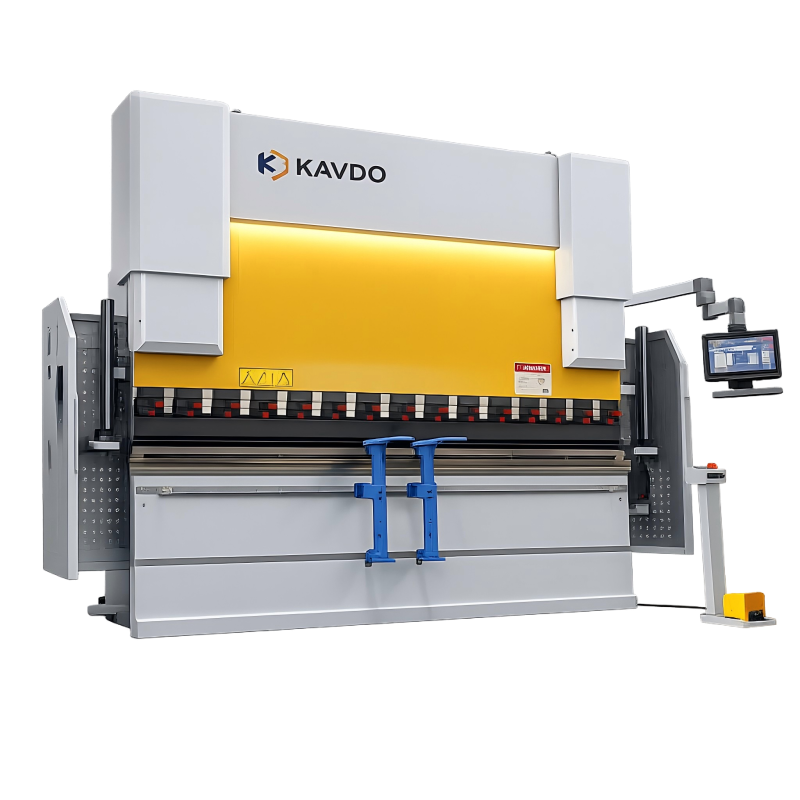
A Synchro Press Brake is a CNC-controlled hydraulic machine tool designed to bend sheet metal by pressing it into a die. The term ‘Synchro’ refers to the synchronization of the two main hydraulic cylinders (designated as the Y1 and Y2 axes) that drive the ram. In a standard hydraulic press brake, maintaining the ram’s level is a challenge, especially when bending off-center. The Synchro Press Brake solves this by using a closed-loop system.
The fundamental architecture involves two independent hydraulic circuits, each controlled by a proportional valve. Linear encoders are mounted on both ends of the machine frame, usually on a separate ‘C-frame’ to isolate them from the main frame’s deflection under load. These encoders provide real-time position data to the CNC controller. If the controller detects even a micron-level deviation between Y1 and Y2, it immediately adjusts the oil flow through the proportional valves to correct the alignment. This constant monitoring happens thousands of times per second, ensuring the ram stays parallel to the bed even under uneven loading conditions.
Precision in bending is not just about force; it is about the real-time dialogue between linear encoders and proportional valves, allowing for dynamic corrections that mechanical systems simply cannot match.
Why the Synchro Press Brake Matters in Sheet Metal Fabrication
For any fabrication shop moving beyond simple 90-degree bends in mild steel, the Synchro Press Brake is indispensable. The primary significance lies in its repeatability and flexibility. Because the machine is CNC-driven, every parameter—ram depth, backgauge position, and crowning compensation—is stored in a program. This reduces setup time from hours to minutes, a critical factor for high-mix, low-volume production environments.
Furthermore, the electro-hydraulic system allows for complex bending sequences that would be impossible on a torsion-bar machine. It handles multi-stage bending and varying material thicknesses with ease. Since the ram can be tilted slightly through the CNC interface (if specific non-parallel bends are required), it offers a level of geometric freedom that is vital for architectural metalwork and aerospace components. The ability to handle off-center loads without damaging the machine frame or compromising the bend angle is perhaps its most significant practical advantage in a busy shop where parts vary in length and position.
Key Factors to Consider When Investing in a Synchro Press Brake
When evaluating a Synchro Press Brake, engineers and purchasing managers must look beyond the basic tonnage and length. Several technical factors define the machine’s true capability:
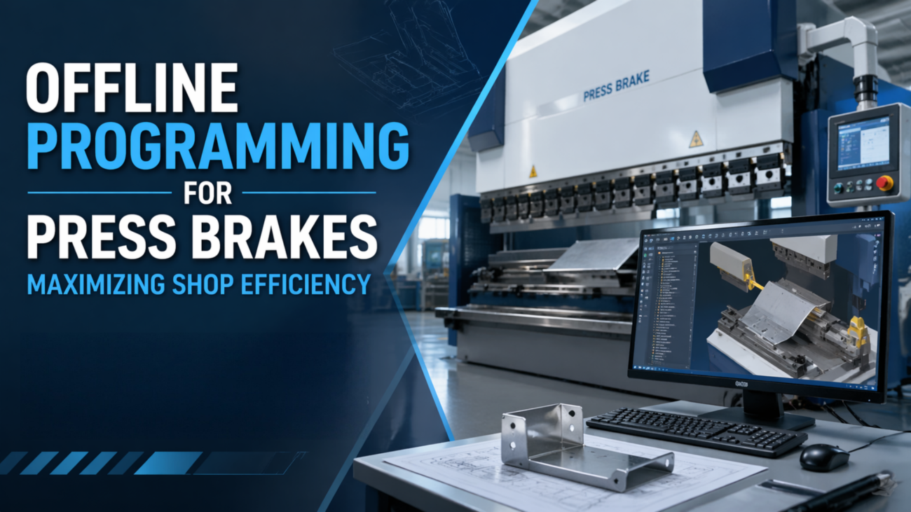
- CNC Controller Complexity: The ‘brain’ of the machine determines how well it handles 3D CAD files, graphic simulations, and automatic bend sequencing. High-end controllers can simulate the entire bending process to detect potential collisions before the first piece of metal is touched.
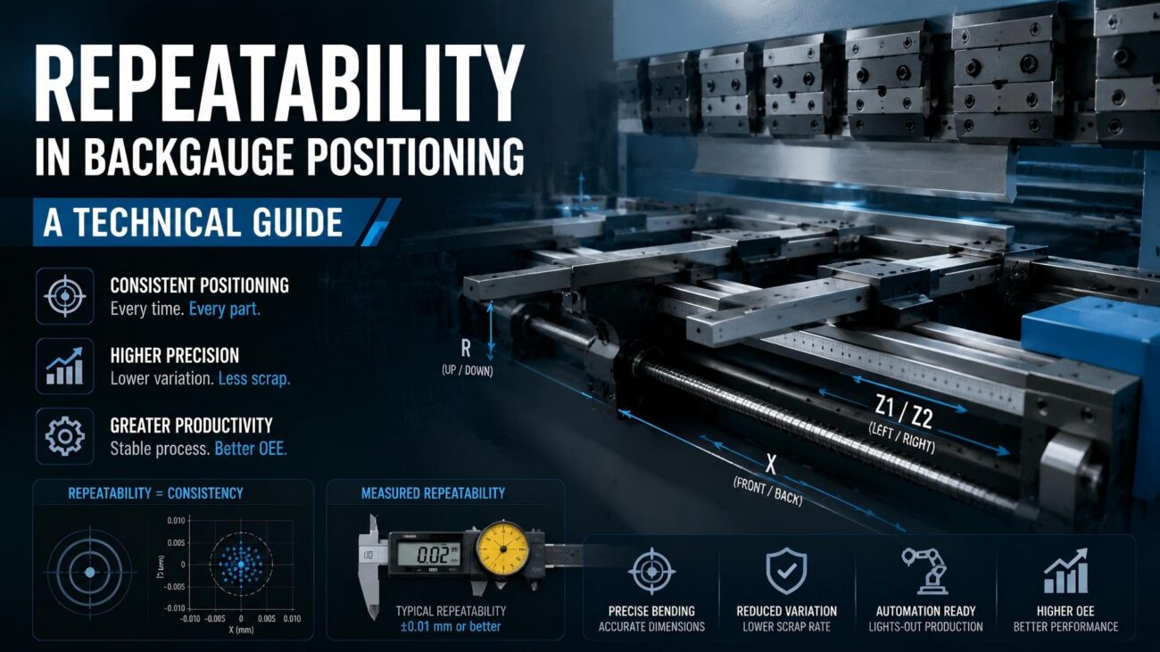
- Backgauge Axes: A standard machine has X and R axes, but advanced models include Z1, Z2, X-Prime, and Delta-X axes. For complex parts, a 6-axis backgauge is often necessary to provide stable gauging points for irregular shapes.
- Crowning System (Anti-Deflection): Even the most rigid frame will deflect slightly under several hundred tons of pressure. A synchro machine must have a crowning system (either hydraulic or mechanical) to compensate for this deflection and ensure a consistent angle across the entire length of the bend.
- Approach and Return Speeds: High-performance synchro brakes feature high-speed approach and return cycles, significantly reducing the ‘air-cut’ time and increasing overall throughput.
Technical Explanation of Electro-Hydraulic Synchronization
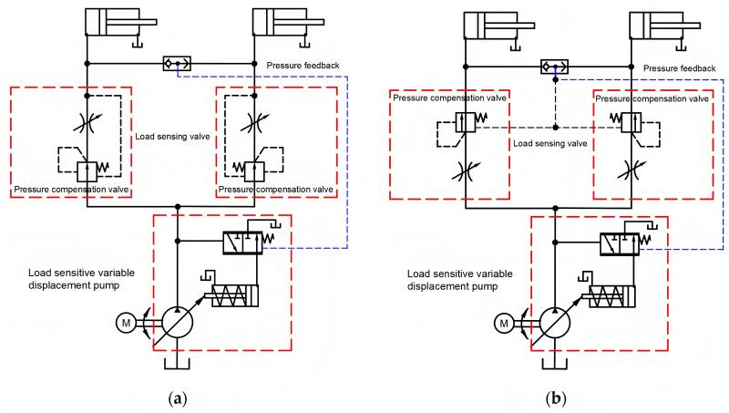
The core of the Synchro Press Brake is the closed-loop feedback system. We can analyze the performance through the relationship between the CNC, the proportional valves, and the linear scales. The linear scale sends the Y1 and Y2 positions to the CNC. The CNC compares these values to the programmed target depth. Any error (E) is processed by the controller’s PID (Proportional-Integral-Derivative) algorithm to output a voltage or current signal to the proportional valves.
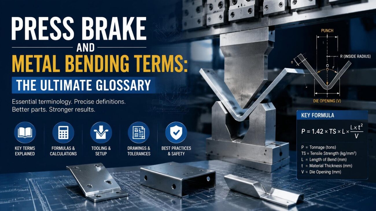
The tonnage required for a bend is a critical calculation for any engineer. The general formula for air bending is:
F = (k * L * s^2 * UTS) / (V * 1000)
Where:
- F: Bending force (Tons)
- k: Material constant (typically 1.42 for mild steel)
- L: Length of the bend (mm)
- s: Material thickness (mm)
- UTS: Ultimate Tensile Strength of the material (N/mm2)
- V: Die opening width (mm)
For example, bending 3mm mild steel over a 24mm die opening for a 1-meter length would require approximately 23 tons of force. A synchro machine manages this force precisely, ensuring that the pressure is distributed correctly even if the part is not centered on the bed.
Technical Data Table: Typical Bending Pressures
| Material Thickness (mm) | Recommended Die Opening (V) | Tonnage per Meter (Mild Steel) | Bending Radius (Approx.) |
|---|---|---|---|
| 1.0 | 8 mm | 8 Tons | 1.3 mm |
| 1.5 | 12 mm | 11 Tons | 2.0 mm |
| 2.0 | 16 mm | 17 Tons | 2.6 mm |
| 3.0 | 24 mm | 23 Tons | 4.0 mm |
| 4.0 | 32 mm | 32 Tons | 5.3 mm |
| 6.0 | 50 mm | 48 Tons | 8.0 mm |
Comparison: Synchro Press Brake vs. Torsion Bar Brake
To understand why the synchro design is superior, it is helpful to compare it to the traditional torsion bar (mechanical-hydraulic) press brake.
| Feature | Torsion Bar Press Brake | Synchro Press Brake |
|---|---|---|
| Synchronization Method | Mechanical Torsion Bar | Electronic/Proportional Valves |
| Axis Control | Limited (usually Y, X) | Multi-axis (Y1, Y2, X, R, Z1, Z2, etc.) |
| Precision | +/- 0.1mm to 0.5mm | +/- 0.01mm |
| Off-center Loading | Risk of machine damage | Automatically compensated |
| Bending Speed | Single speed / Manual control | Variable speed / CNC optimized |
| Setup Time | High (manual depth adjustment) | Low (automated via CNC) |
While torsion bar machines are cost-effective for simple, repetitive work, the Synchro Press Brake is the only choice for shops requiring high accuracy, repeatability, and the ability to work with advanced alloys.
Step-by-Step Guide to Operating a Synchro Press Brake
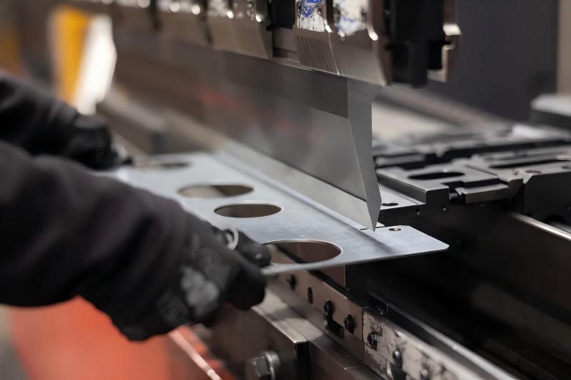
- Pre-Start Inspection: Verify hydraulic oil levels, check the condition of the tooling for chips or cracks, and ensure the safety light curtains are operational.
- Program Entry: Input the material type, thickness, and bend length into the CNC controller. Upload or draw the part profile to generate the bend sequence.
- Tooling Selection: Select the appropriate punch and die based on the machine’s calculation for V-opening and tonnage limits. Securely clamp the tools.
- Calibration/Zeroing: Allow the machine to perform its reference cycle to home the Y1, Y2, and backgauge axes.
- Test Bend: Perform a test bend on a scrap piece of the same material. Measure the resulting angle with a digital protractor.
- Angle Correction: If the angle is off by 0.5 degrees, input the correction into the CNC. The synchro system will adjust the Y1/Y2 depth for all subsequent parts.
- Production Run: Follow the backgauge prompts for each step of the bend sequence, ensuring the sheet is properly seated against the gauge fingers.
Common Mistakes to Avoid
Even with advanced technology, operator and engineering errors can lead to scrap parts or machine damage. Avoid these common pitfalls:
- Ignoring Material Grain Direction: Bending with or against the grain affects the required force and the final bend radius. Always account for grain direction in high-precision parts.
- Using the Wrong V-Opening: Using a die opening that is too small for the material thickness significantly increases tonnage and can crack the material or damage the tooling. The ‘8-times rule’ (V = 8s) is a standard baseline.
- Neglecting Oil Maintenance: The proportional valves in a Synchro Press Brake are highly sensitive to contamination. Failing to change hydraulic filters or monitoring oil temperature can lead to sluggish response times and lost precision.
- Overloading the Center: While synchro machines handle off-center loads well, consistently performing short, high-tonnage bends in the exact center of the bed can cause localized wear or ‘pitting’ of the ram and bed surfaces over many years.
- Improper Crowning Adjustment: Relying solely on the machine’s default crowning settings without verifying the angle at the center versus the ends of the part often results in a ‘canoe’ effect.
Industry Applications
The versatility of the Synchro Press Brake makes it a staple in numerous high-stakes industries:
- Aerospace and Defense: Manufacturing airframe components from high-strength aluminum and titanium alloys where tolerances are measured in hundredths of a millimeter.
- Medical Equipment: Creating stainless steel enclosures and surgical tables that require perfect aesthetic finishes and precise fitment for electronic components.
- Automotive: Producing structural reinforcements and specialized brackets for electric vehicle battery frames where repeatability is key for automated assembly.
- HVAC and Industrial Enclosures: Efficiently bending large panels for ducting and electrical cabinets while maintaining consistency across 3-meter or 4-meter lengths.
Conclusion
The Synchro Press Brake represents the pinnacle of hydraulic bending technology. By integrating high-resolution linear feedback with precise proportional valve control, these machines offer a level of accuracy and versatility that torsion-bar systems cannot match. For any manufacturing facility looking to improve throughput, reduce scrap, and handle complex modern geometries, investing in a high-quality electro-hydraulic synchro machine is a strategic necessity. Understanding the technical nuances—from Y1/Y2 synchronization to tonnage calculations—allows engineers to maximize the potential of these powerful fabrication tools, ensuring long-term competitiveness in an increasingly demanding market.
FAQ
What is the difference between Y1 and Y2 axes on a press brake?
Y1 and Y2 refer to the independent hydraulic cylinders on the left and right sides of the machine. In a Synchro Press Brake, these axes are monitored by separate encoders and controlled by independent valves to ensure the ram stays perfectly level or can be intentionally tilted.
Why do Synchro Press Brakes use linear encoders?
Linear encoders provide high-precision feedback on the actual position of the ram relative to the bed. By measuring the displacement directly, the CNC can compensate for frame deflection and hydraulic variations in real-time to maintain a precise bending angle.
Can a Synchro Press Brake handle off-center bending?
Yes, this is one of its primary advantages. Because the Y1 and Y2 cylinders are controlled independently via a closed-loop system, the machine can detect the resistance of an off-center load and adjust the hydraulic pressure to keep the ram level, preventing damage and maintaining accuracy.
What is the role of the crowning system in a synchro machine?
Crowning compensates for the natural deflection (bowing) of the ram and bed that occurs under high pressure. The crowning system applies an upward force to the center of the bed to ensure the bend angle remains consistent across the entire length of the workpiece.
How does the proportional valve contribute to precision?
Proportional valves can modulate the flow and pressure of hydraulic oil with extreme precision based on electrical signals from the CNC. This allows for smooth speed transitions, accurate ram positioning, and immediate corrections during the bending cycle.