Press Brake Tooling Basics: Guide to Punches and Dies

In the world of precision sheet metal fabrication, the press brake is the workhorse of the shop floor. However, even the most advanced CNC press brake is only as capable as the tooling installed within it. Press brake tooling basics, specifically the relationship between punches and dies, dictate the accuracy, repeatability, and overall quality of the finished part. For engineers and production managers, understanding these components is not merely a matter of operational knowledge but a requirement for optimizing production throughput and extending machine longevity.
Selecting the correct punch and die set is a complex decision-making process involving material science, structural mechanics, and geometry. This article provides an in-depth technical exploration into the mechanics of press brake tooling, offering practical insights for selecting, calculating, and maintaining the tools that form the backbone of modern metalworking. Whether you are working with mild steel, stainless steel, or aluminum, mastering these basics is essential for achieving precise bending angles and consistent results across production runs.
Understanding the Basics of Press Brake Tooling
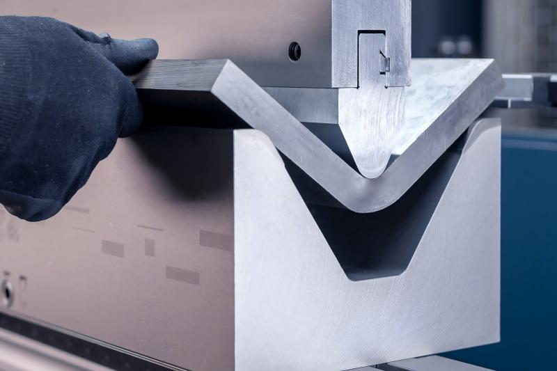
Press brake tooling consists of two primary components: the punch (upper tool) and the die (lower tool). The punch is attached to the moving ram of the press brake, while the die is secured to the bed or bolster. As the ram descends, the punch forces the sheet metal into the cavity of the die, deforming the material into a specific shape—most commonly a V-bend.
The fundamental principle behind this process is localized plastic deformation. When the punch applies pressure, the material exceeds its yield strength but remains below its ultimate tensile strength, allowing it to hold the new shape once the pressure is released. Tooling is categorized by its mounting style, such as American, European (Promecam), or New Standard (Wila/Trumpf), and its geometric profile. Understanding these profiles is the first step in successful tool selection.
Why Press Brake Tooling Basics Matter in Fabrication
Tooling selection directly impacts three critical areas: part accuracy, machine health, and operational safety. Using the wrong tool can result in incorrect bending radii, unsightly surface marking, or even catastrophic tool failure. In high-precision industries like aerospace or medical device manufacturing, a deviation of just half a degree in a bend angle can lead to a rejected batch, resulting in significant financial loss.
The synergy between the punch radius and the die opening determines the final integrity of the workpiece. Choosing the wrong combination doesn’t just ruin the part; it can permanently damage the press brake’s ram or bed through eccentric loading.
Furthermore, understanding tooling basics allows for better design for manufacturability (DFM). When engineers understand the limitations of available punches and dies, they can design parts that are easier and cheaper to produce, avoiding complex setups that require custom-made tools.
Key Factors to Consider in Tooling Selection
Several technical factors must be evaluated before selecting a punch and die set for a specific job:
- Material Type and Tensile Strength: Harder materials like stainless steel require significantly more force to bend than aluminum. The tooling must be rated for the material’s yield strength.
- Sheet Thickness (S): The thickness of the material dictates the minimum die opening required. A general rule of thumb is that the V-opening should be 6 to 8 times the material thickness for materials up to 3mm.
- Bending Radius (Ri): The internal radius of the bend is largely determined by the die opening in air bending. If a specific radius is required, the punch tip radius must also be considered to avoid material fracture.
- Tonnage Capacity: Every tool has a maximum load limit, usually expressed in tons per meter (t/m). Exceeding this limit can cause the tool to explode or shatter.
Technical Calculations for Bending Tonnage

Calculating the required tonnage is the most critical engineering step in press brake operation. The force required to bend a piece of metal depends on the material’s tensile strength, the thickness of the sheet, the length of the bend, and the width of the die opening.
The standard formula for estimating the tonnage (P) required for V-bending is:
P = (K × L × S² × σb) / V
Where:
- P = Bending force (Tons)
- K = Constant factor (usually 1.42 for air bending)
- L = Length of the bend (mm)
- S = Material thickness (mm)
- σb = Tensile strength of the material (kg/mm²)
- V = Die opening width (mm)
Example Scenario: A fabricator needs to bend a 2000mm long piece of 3mm thick mild steel (tensile strength approx. 45 kg/mm²) using a 24mm V-die. The calculation would be: (1.42 × 2000 × 3² × 45) / 24. This provides a baseline to ensure the machine and the tooling can handle the load safely.
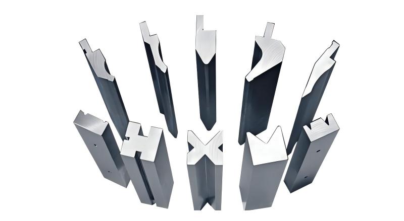
Comparison of Common Die Types
Selecting the right die shape is as important as the tonnage. Different geometries are used for different bending styles and material thicknesses.
| Die Type | Primary Application | Advantages | Disadvantages |
|---|---|---|---|
| Single V-Die | Standard air bending | Versatile, easy to change | Limited to specific thickness ranges |
| Multi-V Die | General job shops | Multiple openings in one block | Heavy and cumbersome to rotate |
| U-Die (Radius Die) | Large radius bends | Smooth curves, no sharp crease | High springback, requires high force |
| Offset (Z-Bend) Tooling | Complex offsets | Forms two bends in one stroke | Requires high tonnage, specific to geometry |
Step-by-Step Guide to Tooling Selection
- Analyze the Part Drawing: Identify the material, thickness, and required internal radius. Note any flanges that might interfere with the punch body.
- Calculate the Required V-Opening: For mild steel, use V = 8 × S. For thinner materials or tighter radii, V = 6 × S may be used.
- Verify Tonnage Requirements: Use the formula provided above to ensure the required force does not exceed the tool’s rated capacity or the machine’s limits.
- Select the Punch Profile: Choose a punch with a tip radius close to the desired internal bend radius. Ensure the punch shape (e.g., gooseneck, straight, or acute) allows for the necessary clearance for existing bends.
- Check for Interference: Use simulation software or manual layout to ensure the part won’t hit the punch or the machine frame during the stroke.
Common Mistakes to Avoid
Even experienced operators can make mistakes that lead to scrap or equipment damage. One of the most common errors is bottoming with air-bend tooling. Attempting to force a punch deeper into a die than the material allows can cause tonnage to spike exponentially, leading to tool breakage.
Maintenance is often overlooked. Micro-cracks in punches or debris in die cavities can cause localized stress concentrations, leading to catastrophic tool failure under load.
Another frequent mistake is incorrectly estimating springback. All materials exhibit some level of springback. If the tooling doesn’t allow for over-bending (especially in air bending), the final part will not meet the specified angle.
Industry Applications
Press brake tooling is utilized across various sectors, each with unique requirements:
- Automotive: High-strength steel components require heavy-duty, wear-resistant tooling for structural frames.
- Aerospace: Requires precision-ground tooling to handle thin-gauge aluminum and titanium with zero-tolerance for surface marring.
- Food and Medical: Often uses specialized dies with nylon inserts or protective tapes to prevent carbon contamination on stainless steel surfaces.
- Construction: Heavy-duty large V-dies are used to form thick plates for structural beams and earth-moving equipment.
Conclusion
Mastering press brake tooling basics is a journey of understanding the interaction between force, geometry, and material behavior. By selecting the correct punch and die combinations and adhering to rigorous tonnage calculations, manufacturers can ensure high-quality parts, reduced waste, and a safer working environment. As materials become stronger and part geometries more complex, the role of the technical engineer in selecting and maintaining the right tooling becomes more vital than ever. Investing in high-quality, precision-ground tooling is not an expense—it is a strategic investment in the long-term efficiency of your fabrication operations.
FAQ
How do I choose the right V-opening for my die?
The standard industry rule is to choose a V-opening 8 times the material thickness (8S) for mild steel between 0.5mm and 8mm thick. For thicker materials, 10S or 12S is often used to reduce the required bending force.
What is the difference between air bending and bottoming?
Air bending only contacts the material at three points (the punch tip and the two edges of the die), allowing for various angles with one tool. Bottoming presses the material fully into the die shape, requiring more force but offering higher angular accuracy.
Can I use the same punch for different material thicknesses?
Yes, in air bending, the same punch can be used for different thicknesses as long as the punch tip radius is appropriate for the material and the tonnage limits are not exceeded.
Why is the punch tip radius important?
If the punch tip radius is too sharp (smaller than the material’s natural minimum bend radius), it can ‘pierce’ or crease the material, leading to structural weakness or cracking along the bend line.
How often should press brake tooling be inspected?
Tooling should be inspected daily for debris and weekly for signs of wear, deformation, or micro-cracks. Precision-ground tools require careful handling to maintain their accuracy over time.


