Press Brake Crowning: Essential Deflection Compensation Science


In high-precision sheet metal fabrication, maintaining a consistent bend angle across the entire workpiece is a major challenge. Under heavy tonnage, a press brake’s ram and bed experience elastic deflection, causing uneven bending—often wider in the center than at the ends. This “canoeing” effect can compromise part accuracy. Press Brake Crowning is the engineered solution that compensates for this deformation, keeping the tooling perfectly parallel under load and ensuring uniform bending results.
Understanding the Basics of Press Brake Crowning
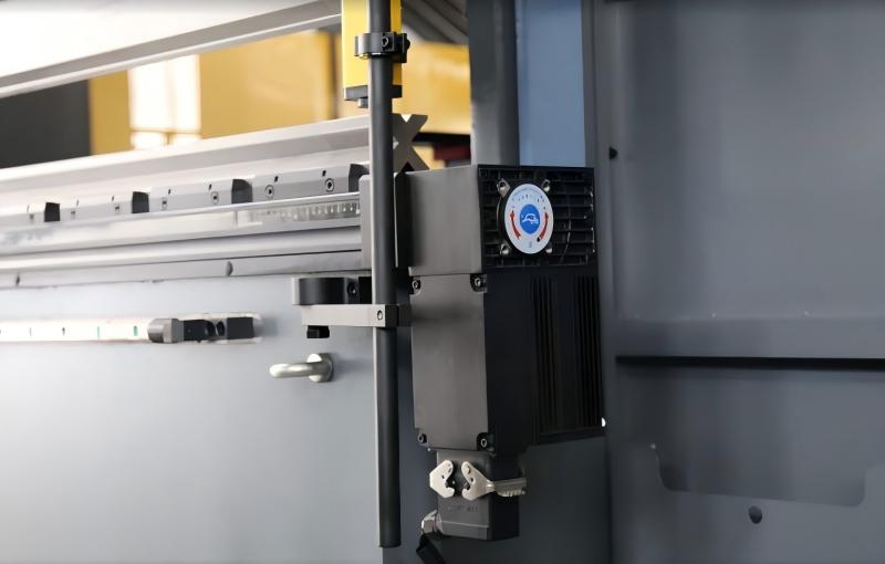
To understand Press Brake Crowning, I view the machine as a structural system. When the ram is driven downward, force is applied mainly at the sides, while resistance is spread along the die. This causes slight deflection: the ram bows upward and the bed bends downward in the center. The result is a gap in the middle of the tooling, leading to inconsistent angles—such as achieving 90° at the ends but 92–93° in the center.
Deflection is not a sign of a weak machine; it is an inevitable physical reality of applying high-tonnage loads to steel structures. The goal of crowning is to introduce a compensatory curve that matches the deflection curve perfectly.
Crowning systems work by intentionally curving the bed or the ram upward in the center. By creating this ‘crown,’ the machine compensates for the inevitable ‘sag’ that occurs during the stroke. When the machine reaches its full tonnage, the induced crown and the natural deflection cancel each other out, resulting in a perfectly straight and parallel relationship between the punch and the die.
Why Press Brake Crowning Matters in Fabrication
The practical significance of crowning cannot be overstated for any shop handling parts longer than 1 meter or utilizing high-strength materials. Without precise deflection compensation, the resulting parts will fail to meet tight tolerances, leading to several downstream production issues. Inconsistent angles make welding fixtures difficult to use, as parts will not align properly. For engineers designing complex assemblies, these variations can lead to structural weaknesses or the need for excessive grinding and manual correction.
Furthermore, as the industry moves toward high-strength, low-alloy (HSLA) steels and thicker materials, the tonnage required increases exponentially. Higher tonnage means greater deflection. Modern CNC press brakes rely on automated crowning systems to maintain throughput; without them, operators would spend hours shimming dies with paper or thin metal strips—a manual process that is both inefficient and inconsistent. Implementing robust Press Brake Crowning technology allows for ‘first-part, right-part’ manufacturing, which is critical for lean operations and reducing material waste.
Key Factors to Consider in Deflection Compensation
Several technical variables dictate the amount of compensation required for a specific job. Engineers and operators must account for these when programming the machine or selecting a crowning system:
- Machine Length: The longer the distance between the side housings, the greater the potential for deflection. A 4-meter machine will experience significantly more bowing than a 2-meter machine under the same load per meter.
- Material Tensile Strength: Harder materials, such as Stainless Steel 304 or Hardox, require much higher bending forces than mild steel or aluminum. Increased force leads directly to increased deflection.
- Die Opening (V-width): A narrower V-die requires more tonnage to form the same material thickness. This increased pressure necessitates a more aggressive crowning adjustment.
- Sheet Thickness: As thickness increases, the force required to reach the yield point of the material increases, putting more stress on the ram and bed.
- Machine Bed Rigidity: The moment of inertia of the bed and ram structures determines their natural resistance to bending. Higher-quality machines often feature deeper beds to minimize the deflection constant.
Technical Explanation and Deflection Calculation
The deflection of a press brake ram can be modeled using the principles of solid mechanics, specifically the formula for a beam supported at two ends with a distributed load. While modern CNC controllers handle these calculations in real-time, the underlying physics follows this relationship:
Deflection (d) = (5 * q * L^4) / (384 * E * I)
Where:
- q represents the load per unit length (Tons/meter).
- L is the distance between the side frames.
- E is the Young’s Modulus of the machine’s steel (approx. 210 GPa).
- I is the Moment of Inertia of the beam’s cross-section.
From this formula, we can see that deflection increases with the fourth power of the length (L^4). This explains why long-bed machines are so sensitive to crowning accuracy. In a CNC-controlled crowning system, the computer uses the material type, thickness, and length entered by the operator to calculate the expected ‘q’ and ‘d’, then adjusts the crowning mechanism to provide an equal and opposite displacement.
Comparison of Crowning Technologies
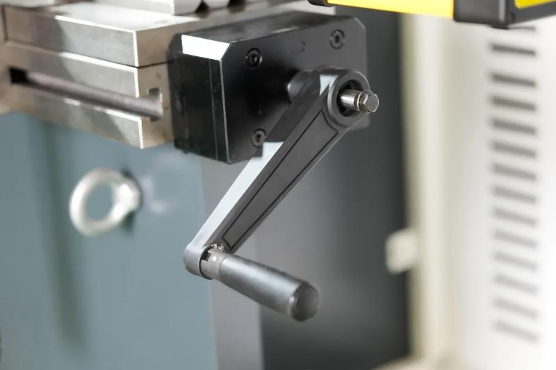
There are two primary methods for achieving deflection compensation in modern press brakes: Hydraulic and Mechanical. Both aim to solve the same problem but utilize different engineering approaches.
| Feature | Hydraulic Crowning | Mechanical (Wedge) Crowning |
|---|---|---|
| Mechanism | Multiple hydraulic cylinders located in the lower bed. | A series of sliding offset wedges controlled by a motor. |
| Adjustment | Dynamic; can adjust during the bend cycle. | Static; set before the bend cycle begins. |
| Precision | Very high; localized pressure points. | Extremely high; follows a predefined curve. |
| Durability | Requires seal maintenance over time. | Highly durable; purely mechanical movement. |
| Reaction Speed | Instantaneous response to pressure changes. | Slower; requires motorized positioning. |
Hydraulic crowning is often preferred for high-speed, variable-load applications because the CNC can modulate the pressure in the compensation cylinders on the fly. Mechanical crowning, often referred to as ‘Wedge Crowning,’ uses a series of precision-ground wedges that create a perfect parabolic curve. Mechanical systems are highly regarded for their long-term stability and resistance to temperature-related fluctuations in hydraulic fluid viscosity.
Step-by-Step Guide to Optimizing Crowning
To achieve the best results with your press brake crowning system, follow this professional procedure:
- Verify Machine Leveling: Before addressing crowning, ensure the machine is perfectly leveled and anchored. An unlevel bed can introduce twisting forces that crowning cannot fix.
- Input Accurate Material Data: The CNC crowning calculation is only as good as the data provided. Measure the actual thickness of your material with calipers, as a 0.1mm difference can impact the tonnage and deflection.
- Zero-Load Calibration: Ensure the crowning system is at its ‘zero’ state when no load is applied. For mechanical systems, this means the wedges are at their baseline position.
- Perform a Test Bend: Use a test strip of the same length as your final part. Measure the angle at the ends and in the exact center.
- Incremental Adjustment: If the center angle is wider (e.g., 92 degrees vs 90 degrees at the ends), increase the crowning value. Most modern controllers allow you to input the ‘angle deviation’ directly, and the software will calculate the necessary compensation.
- Monitor Tonnage: If the machine hits the tonnage limit too early, the crowning might be over-active, causing the punch to bottom out in the center before the ends.
Common Mistakes in Press Brake Crowning
Even experienced operators can make errors when managing deflection compensation. One of the most common mistakes is over-crowning. This occurs when the compensation exceeds the deflection, causing the center angle to be tighter than the ends (e.g., 88 degrees in the center and 90 at the ends). This can actually damage the tooling or the machine bed if excessive force is concentrated in the center.
Another frequent error is ignoring grain direction. Metal behaves differently when bent with or against the grain. While crowning compensates for machine deflection, it cannot compensate for material inconsistencies. If your crowning is set correctly but you see variations, check if your blanks were nested in different orientations on the laser or plasma table.
Finally, failing to lubricate mechanical crowning wedges can lead to sticking. If the wedges do not move smoothly, the curve will be stepped rather than a smooth parabola, resulting in ‘waves’ in the bend angle across the length of the part.
Industry Applications for Press Brake Crowning
Press brake crowning is vital across various sectors where structural integrity and aesthetic precision are paramount:
- Aerospace: Components for airframes often require extremely long, precise bends in high-strength aluminum alloys. Even a 0.5-degree variation can lead to assembly failure.
- Heavy Construction: Manufacturing booms for cranes and chassis for long-haul trailers involves thick plates (12mm to 25mm) where deflection forces are immense.
- Pole and Tower Manufacturing: Lighting poles and telecommunication towers are formed from long sheets (6m to 12m). Crowning is the only way to ensure these tapered sections fit together perfectly for telescoping joints.
- Kitchen and Medical Equipment: Stainless steel fabrication requires perfect angles for hygienic welding. Crowning prevents the ‘gaps’ that would otherwise occur in long countertop or cabinet bends.
Conclusion
Press brake crowning is not merely a feature; it is a fundamental requirement for any serious sheet metal operation. Understanding the science of deflection allows engineers and managers to make informed decisions about machinery investments and production processes. By choosing the right compensation system—whether hydraulic or mechanical—and maintaining a disciplined approach to calibration and material data, fabricators can eliminate the ‘canoeing’ effect, reduce scrap, and deliver parts that meet the highest industrial standards. As materials become stronger and tolerances tighter, the mastery of deflection compensation will continue to be a defining factor in manufacturing excellence.
FAQ
What is the canoeing effect in press brake bending?
The canoeing effect refers to a bend where the angle in the center of the sheet is wider (less bent) than at the ends, caused by the machine bed and ram deflecting away from each other under pressure.
Can I retrofit an old press brake with a crowning system?
Yes, many manufacturers offer bolt-on mechanical crowning beds (also called crowning tables) that can replace the existing bottom rail on older manual or CNC press brakes to improve accuracy.
Does crowning help with springback?
No, crowning specifically addresses machine deflection. Springback is a material property. However, a properly crowned machine ensures that springback is consistent across the entire length, making it easier to compensate for in the CNC controller.
How do I know if I need hydraulic or mechanical crowning?
Hydraulic crowning is excellent for high-volume jobs with varying lengths due to its speed. Mechanical crowning is often preferred for heavy-duty, high-tonnage applications where extreme long-term precision and stability are required.
What happens if the crowning is set too high?
Over-crowning will cause the center of the part to be over-bent (a tighter angle) compared to the ends. It also increases wear on the center of your tooling and can potentially damage the machine if pushed to extreme limits.