Press Brake Automation Guide: Boosting Productivity with CNC Controls and Offline Programming

Technical Overview of Press Brake Automation
In the modern era of metal fabrication, the transition from manual operation to high-level automation is no longer a luxury but a necessity for staying competitive. Press brake automation, specifically through the integration of advanced CNC (Computer Numerical Control) systems and offline programming (OLP), represents the pinnacle of efficiency in sheet metal bending. At HARSLE, we recognize that the heart of a productive workshop lies in the seamless communication between the design office and the shop floor. Automation reduces the ‘art’ of bending—which traditionally relied on the tribal knowledge of veteran operators—into a precise, repeatable science.
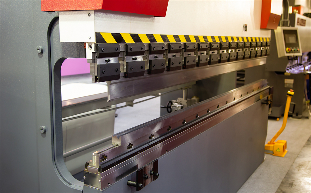
The technical foundation of an automated press brake involves several key components: the CNC controller, the multi-axis backgauge system, and the hydraulic compensation (crowning) mechanism. Modern CNC controllers, such as those from Delem, Cybelec, or ESA, act as the brain of the machine. They process complex algorithms to control the Y1 and Y2 cylinders independently, ensuring that the ram remains perfectly level or tilted to a specific degree if required. This synchronization is achieved through high-resolution linear encoders that provide real-time feedback to the controller, allowing for adjustments within microns.
Offline programming is the second pillar of this automation guide. Traditionally, an operator would spend 30 to 60 minutes at the machine, manually inputting dimensions, calculating bend sequences, and performing test bends. With offline programming software, this entire process is moved to a computer workstation. The software takes a 3D CAD model, automatically unfolds it, determines the optimal bend sequence, selects the appropriate tooling from a digital library, and checks for potential collisions. This data is then transferred to the press brake via a network or USB, reducing setup time to mere minutes.
Furthermore, automation extends to the physical handling of parts. While this guide focuses on controls and software, it is important to note that CNC systems are the prerequisite for robotic integration. A CNC-controlled press brake can communicate with a robotic arm, allowing for 24/7 lights-out manufacturing. The synergy between high-speed hydraulics, precision electronics, and intelligent software creates a production environment where scrap is minimized, and throughput is maximized.
Core Parameters of Automated Press Brakes
Understanding the core parameters of a CNC press brake is essential for any engineer or shop manager looking to optimize their production line. These parameters define the machine’s capability and its compatibility with automated workflows. The first and most critical parameter is Tonnage. Tonnage refers to the maximum pressure the press brake can exert. In an automated environment, the CNC system must accurately calculate the required tonnage for each bend to prevent machine overload and tool damage.
The second parameter is the Bending Length, which is the maximum width of the sheet metal the machine can accommodate. However, in the context of automation, the ‘Distance Between Uprights’ is equally important, as it determines whether a part can pass through the machine during a complex bending sequence. Automated systems often utilize multi-axis backgauges (X, R, Z1, Z2, X5, etc.) to position the workpiece accurately. The speed and precision of these axes directly impact the cycle time of each part.
Stroke and Open Height are also vital. A larger open height allows for the use of deep box tools and facilitates the easy removal of large, complex parts by automated handling systems. Additionally, the Approach Speed, Bending Speed, and Return Speed are parameters that can be fine-tuned within the CNC controller. High-speed machines use servo-hydraulic systems to transition quickly between these phases, significantly reducing the ‘air-cut’ time during the bending cycle.
Finally, the Crowning System (Deflection Compensation) is a core parameter that ensures consistency across the entire length of the bend. In an automated setup, the CNC controller calculates the deflection of the bed and ram based on the material thickness and length, then adjusts the mechanical or hydraulic crowning system automatically. This eliminates the need for manual shimming, which is a major bottleneck in traditional bending operations.
Calculation Method for Bending Force
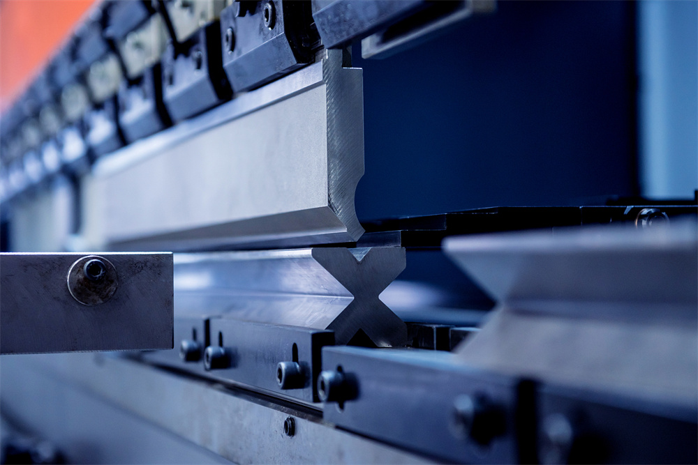
To successfully automate a bending process, the CNC controller must be fed accurate data regarding the bending force required. While the software usually handles this, understanding the underlying physics is crucial for troubleshooting and tool selection. The standard formula for calculating the bending force (P) for air bending of mild steel is:
P = (650 * S² * L) / V
- P: Bending force in Kilonewtons (kN).
- S: Material thickness in millimeters (mm).
- L: Bending length in meters (m).
- V: V-die opening width in millimeters (mm).
For example, if you are bending a 3mm thick mild steel plate over a 2-meter length using a 24mm V-die, the calculation would be: P = (650 * 3² * 2) / 24 = 487.5 kN (approximately 50 tons). It is important to note that different materials require different constants. Stainless steel, for instance, typically requires about 50% more pressure than mild steel, so the constant 650 would be replaced by approximately 1000.
In offline programming, the software also calculates the ‘Minimum Flange Length’ based on the V-opening. The rule of thumb is that the internal flange must be at least 0.7 to 1.0 times the V-opening to ensure the material doesn’t slip into the die. Automated systems use these calculations to warn the designer if a part is unmanufacturable before it ever reaches the shop floor, saving time and material.
Parameter Table for HARSLE WE67K Series
The following table outlines the technical specifications for the HARSLE WE67K series, which is our flagship line of CNC synchronized press brakes designed for high-productivity automation.
| Model (WE67K) | Nominal Pressure (kN) | Length (mm) | Upright Distance (mm) | Throat Depth (mm) | Ram Stroke (mm) | Max Open Height (mm) |
|---|---|---|---|---|---|---|
| 63T/2500 | 630 | 2500 | 2000 | 320 | 150 | 350 |
| 100T/3200 | 1000 | 3200 | 2600 | 320 | 200 | 400 |
| 160T/3200 | 1600 | 3200 | 2600 | 400 | 200 | 450 |
| 200T/4000 | 2000 | 4000 | 3100 | 400 | 250 | 500 |
| 300T/6000 | 3000 | 6000 | 4800 | 500 | 300 | 600 |
Common Engineering Mistakes in Press Brake Automation
One of the most frequent mistakes in press brake automation is the failure to account for material grain direction. Sheet metal has a grain direction resulting from the rolling process at the mill. Bending with the grain requires less force but increases the risk of cracking, while bending against the grain requires more force but results in a stronger bend. Offline programming software can track this, but only if the initial CAD layout is oriented correctly. Ignoring this leads to inconsistent angles and structural failures in the finished product.
Another common error is neglecting the ‘Springback’ factor. Every material has a degree of elasticity; when the pressure is released, the metal slightly returns to its original shape. While modern CNC controls have built-in springback databases, these are often based on ideal material conditions. In reality, material properties vary between batches. Advanced automation systems now use angle-measuring sensors (like lasers) to measure the bend in real-time and automatically over-bend to compensate for springback. Failing to utilize these sensors or failing to calibrate the software for specific material batches leads to high scrap rates.
Tooling mismatch is also a significant issue. Automation relies on the assumption that the physical tools in the machine exactly match the digital tools in the software. If an operator swaps a punch or die without updating the CNC controller, the collision detection system becomes useless. This can result in catastrophic damage to the machine or the tools. Furthermore, using worn-out tooling in an automated process is counterproductive, as the CNC cannot compensate for physical irregularities in the tool’s radius or V-shape.
Finally, many facilities fail to invest in proper training for the transition to offline programming. They treat the software as a simple drawing tool rather than a complex simulation engine. Without a deep understanding of how the software calculates bend deductions and sequences, engineers may produce programs that are theoretically possible but practically difficult for the machine to execute, leading to frustration on the shop floor and a decrease in overall productivity.
Selection Checklist for Automated Press Brakes
When selecting a press brake for an automated environment, use the following checklist to ensure the machine meets your long-term production goals:
- Controller Capability: Does the controller support 3D visualization and network connectivity? Is it compatible with industry-standard offline programming software like Delem Profile-T or MetaBEND?
- Backgauge Axes: For complex parts, a 4-axis (X, R, Z1, Z2) or 6-axis backgauge is essential. Ensure the backgauge has high positioning speed and repeatability (±0.01mm).
- Crowning System: Opt for an automatic CNC-controlled crowning system (either hydraulic or mechanical) to ensure consistent angles across long workpieces.
- Safety Integration: Does the machine include laser safety guards (e.g., DSP or Lazersafe) that integrate with the CNC to allow for high-speed closing without compromising operator safety?
- Tooling Compatibility: Ensure the machine uses a standard clamping system (like Amada/Promecam or Wila) that allows for quick tool changes and is widely supported by software libraries.
- Hydraulic System: Look for servo-driven hydraulic systems. These are quieter, consume less energy, and provide faster response times for the Y-axis synchronization.
- Expandability: Is the CNC controller ready for future robotic integration? Does it have the necessary I/O ports and communication protocols (like OPC UA)?
Frequently Asked Questions (FAQ)
1. What is the main advantage of offline programming for press brakes?
The primary advantage is the drastic reduction in machine downtime. By preparing programs on a PC while the machine is still running another job, you eliminate the ‘setup bottleneck.’ It also allows for collision testing and sequence optimization before the first piece of metal is even touched.
2. Can I automate an old hydraulic press brake?
While some retrofitting is possible (such as adding a new CNC controller and backgauge), it is often more cost-effective to invest in a modern machine. Older machines lack the high-speed hydraulics and frame rigidity required to take full advantage of modern automation software.
3. How does CNC crowning improve productivity?
CNC crowning automatically compensates for the natural deflection of the machine frame under load. Without it, operators must manually place thin strips of paper or metal (shimming) under the die to get a straight bend, a process that can take hours on long parts. CNC crowning does this in milliseconds.
4. Is 3D software necessary, or is 2D sufficient?
For simple brackets, 2D is sufficient. However, for complex parts with multiple bends in different directions, 3D software is essential for accurate collision detection and to visualize the part’s orientation during the bending sequence.
5. What maintenance does an automated press brake require?
Beyond standard hydraulic oil changes and lubrication, automated machines require regular calibration of the backgauge axes and the Y1/Y2 linear encoders. It is also vital to keep the CNC software and offline programming tools updated to the latest versions to ensure compatibility and access to new features.


