Deconstructing the Press Brake Bending Cycle for Efficiency


In industrial sheet metal fabrication, production efficiency is often measured in seconds, and the bending cycle plays a central role in achieving high productivity. A press brake bending cycle is not a simple movement but a precisely controlled sequence consisting of three key phases: rapid approach, working stroke, and return stroke. Each phase is engineered to balance speed, accuracy, and safety. For engineers and factory managers, understanding these stages is essential for optimizing throughput, reducing cycle time, and ensuring consistent part quality. With modern CNC systems, these phases can be finely adjusted to achieve higher precision and repeatability. This article breaks down the bending cycle, explaining its mechanics, key calculations, and practical optimization strategies.
Understanding the Basics of the Bending Cycle

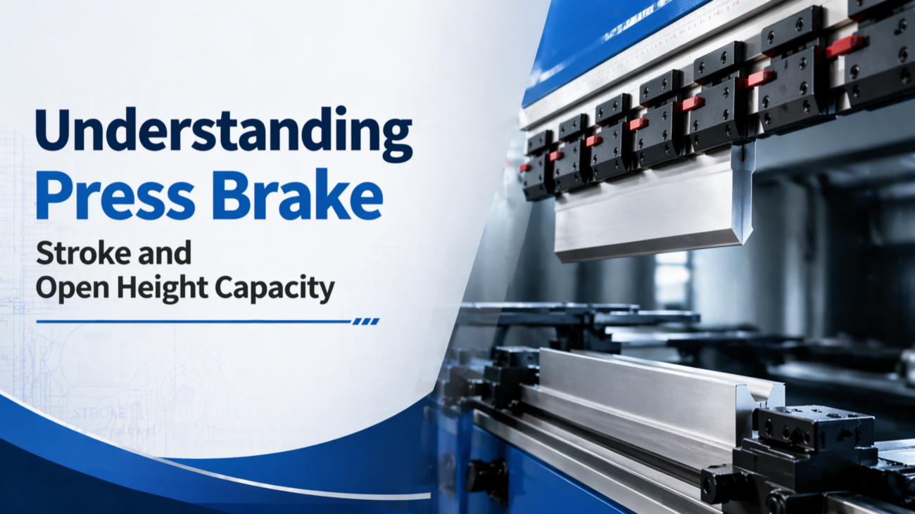
The bending cycle describes the complete movement of a press brake ram from top dead center (TDC), through material deformation, and back to its starting position. It is divided into three key phases. First, the rapid approach allows the ram to move quickly toward the workpiece, reducing idle time. Second, the pressing phase slows the motion to ensure controlled deformation and high precision. Finally, the return stroke brings the ram back to its original position. These stages are controlled by hydraulic or electric drive systems under CNC supervision. Critical transition points, such as the mute point before material contact, ensure safety and accuracy. Understanding this cycle involves knowledge of hydraulic flow behavior or servo motor performance characteristics.
Why the Bending Cycle Matters in Sheet Metal Fabrication
The efficiency of the bending cycle has a direct impact on cost per part and overall production capacity. In high-volume manufacturing, saving even one second per cycle can significantly increase output over time. However, speed alone is not the only factor. The dynamics of each phase also affect bend quality. An abrupt transition from rapid approach to pressing can cause impact marks or tooling damage, while excessive pressing speed may result in cracks or inconsistent springback. In addition, proper decompression at the end of the stroke is critical to safely release stored energy. Poor decompression control can lead to hydraulic shock, reducing the lifespan of key components such as valves and seals.
In modern fabrication, the machine is only as productive as the software governing its motion. Optimizing the bending cycle is where engineering theory meets shop floor reality.
Key Factors to Consider in Cycle Optimization
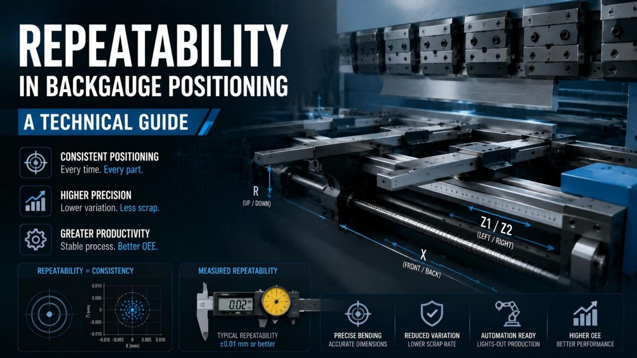
Several technical factors determine the performance of the bending cycle. First is ram speed, usually measured in mm/s, with high-end machines reaching over 200 mm/s during rapid approach. Second is CNC response time, as the controller must process feedback instantly to regulate hydraulic flow or servo output. Third, material properties such as thickness and tensile strength influence required tonnage and optimal pressing speed. Fourth, backgauge synchronization is essential to ensure accurate positioning before bending begins. Finally, cooling and filtration systems play an indirect but important role, as overheating or contaminated hydraulic oil can affect viscosity, leading to unstable or inconsistent ram movement during extended production runs.
Technical Calculation of the Bending Cycle Time
To estimate production capacity, engineers must calculate the total bending cycle time by summing each phase of the process. The formula is: T = (D1/V1) + (D2/V2) + (D3/V3) + DT + DC, where each variable represents distances, speeds, dwell time, and decompression time. This calculation helps determine how long a single bend takes under specific machine settings. For example, with defined approach, pressing, and return speeds, the total cycle may be around a few seconds per bend. Although this provides a clear baseline for machine performance, it does not include material handling or operator time, which must be added to evaluate the full production efficiency accurately.
Tonnage and Speed Correlations
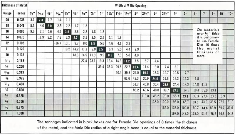
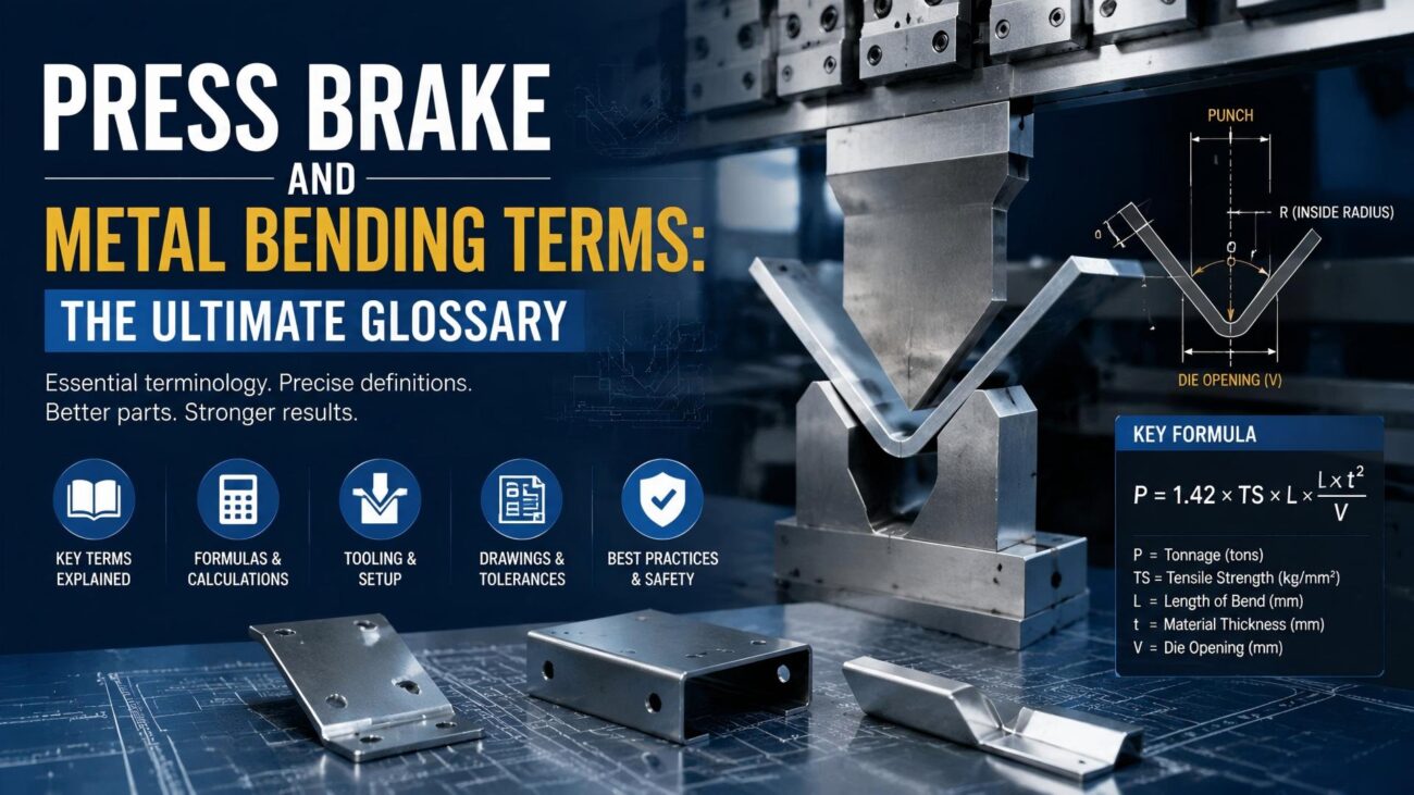
It is also important to understand how tonnage relates to the cycle. The pressing speed is often limited by the available flow rate of the hydraulic pump at a given pressure. The required tonnage (P) can be estimated using the formula: P = (1.42 * Rm * S^2 * L) / V. Here, Rm is the material tensile strength (N/mm2), S is the sheet thickness (mm), L is the bend length (mm), and V is the die opening (mm). As the required tonnage increases, the machine may automatically slow the pressing speed to maintain constant power output (P = Force * Velocity).
| Phase Name | Function | Typical Speed Range | Critical Safety Point |
|---|---|---|---|
| Rapid Approach | Minimize travel time | 100 – 250 mm/s | Mute Point Setting |
| Pressing Stroke | Actual deformation | 1 – 15 mm/s | Tonnage Limit |
| Decompression | Release stored energy | N/A (Pressure drop) | Valve Timing |
| Return Stroke | Clearance for next part | 80 – 180 mm/s | Backgauge Retract |
Comparison of Machine Drive Technologies
The dynamics of the bending cycle vary significantly between machine types. Conventional hydraulic press brakes use proportional valves to control the flow of oil. While reliable, they have inherent latency due to fluid compressibility. Hybrid press brakes utilize servo-motors to drive the hydraulic pumps, allowing for faster response times and energy savings during the dwell and return phases. All-electric press brakes represent the pinnacle of cycle efficiency. Because they use ball screws or belt drives powered by servo-motors, they can accelerate and decelerate the ram almost instantaneously. This allows for a much tighter transition between the rapid approach and pressing phases, often reducing cycle times by up to 30 percent compared to traditional hydraulic systems.
| Feature | Hydraulic Drive | Hybrid Drive | Electric Drive |
|---|---|---|---|
| Acceleration | Moderate | High | Very High |
| Cycle Consistency | Varies with Temp | High | Extremely High |
| Energy Usage | High (Continuous Pump) | Low (On-demand) | Lowest (Direct) |
| Maintenance | Filter/Seal changes | Minimal Fluid work | Mechanical lubrication |
Step-by-Step Guide to Optimizing the Bending Cycle
Optimizing the bending cycle requires careful adjustment of several key parameters. First, calibrate the mute point as close as possible to the material surface, typically 2–3 mm, to reduce idle movement while maintaining safety. Second, optimize decompression settings based on material properties, as high-strength materials require longer release time to prevent hydraulic shock. Third, fine-tune backgauge retract so it moves slightly during clamping, avoiding contact damage during return. Fourth, use variable return heights instead of full top dead center travel to save time. Finally, synchronize multi-bend operations by coordinating backgauge movement with ram return, ensuring continuous and efficient production flow.
Common Mistakes to Avoid in Cycle Programming
A common mistake in press brake operation is setting the pressing speed too high, especially for short-flange bends, which can cause the material to whip upward and create inconsistent angles or safety risks. Another issue is neglecting dwell time when bending thick materials; without sufficient holding time at the bottom, springback increases and accuracy decreases. Operators also often misadjust the mute point, either setting it too high and wasting cycle time or bypassing it entirely, which can damage tooling or the machine. Additionally, ignoring oil temperature variations in hydraulic systems can lead to cycle drift, where bending results change throughout the day. Proper warm-up procedures help maintain consistency.
Precision is not about moving fast; it is about stopping exactly where you intended to, every single time.
Industry Applications and Practical Scenarios

In the automotive industry, where cycle times are scrutinized to the millisecond, high-speed hybrid benders are used to produce structural components with rapid-fire consistency. In these environments, the bending cycle is integrated with robotic loaders, requiring perfect synchronization between the ram return and the robot’s entry into the work envelope. In the aerospace sector, the focus shifts to the pressing phase, where very slow speeds are used to prevent micro-cracking in specialized alloys like Titanium or Inconel. For general enclosure manufacturing, such as electrical cabinets, the use of ‘multi-step’ programming allows the ram to hover just above the sheet between folds, significantly increasing the parts-per-hour rate for complex geometries.
Conclusion and Recommendations
Deconstructing the bending cycle shows that every moment of ram movement can be optimized to improve performance. By refining the transitions between rapid approach, pressing, and return, manufacturers can achieve an ideal balance of speed, accuracy, and safety. Advanced electric or hybrid press brakes offer significant improvements in cycle efficiency, but even traditional hydraulic machines can be optimized through precise programming of mute points, decompression, and return heights. Conducting a detailed time study of common bending operations helps identify unnecessary delays within the cycle. Eliminating this “dead time” is one of the most effective ways to boost productivity and improve overall profitability.
FAQ
What is the mute point in a bending cycle?
The mute point is the specific position in the ram’s descent where it switches from a high-speed rapid approach to a slower, controlled pressing speed, usually set just above the material surface for safety and precision.
Why is decompression necessary after the pressing phase?
Decompression allows the built-up hydraulic pressure and the elastic energy stored in the machine frame and workpiece to be released gradually, preventing hydraulic shock and ensuring a smooth return stroke.
How does pressing speed affect the quality of a bend?
Pressing speed influences the rate of material deformation; too high a speed can lead to material cracking or inconsistent spring-back, especially in high-tensile alloys or stainless steel.
Can I increase the return speed on any press brake?
Return speed is limited by the machine’s hydraulic flow capacity or the torque limits of the servo-motors. While it can be adjusted in the CNC, exceeding factory limits can cause vibration and reduce machine lifespan.
What is the advantage of a hybrid drive in the bending cycle?
Hybrid drives use servo-controlled pumps that only run when movement is required, providing faster acceleration and deceleration between cycle phases compared to traditional constant-run hydraulic systems.